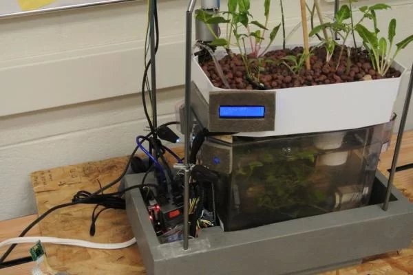
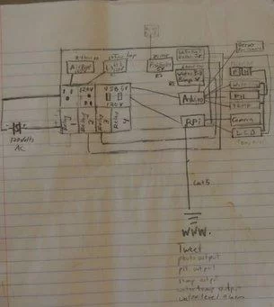
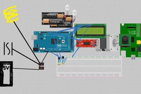
We are creating an automated Aqua Garduino Mini system with mobile updates via Twitter. Sensors and motors will be controlled from an Arduino while the entire system, including mobile updates, will be orchestrated by a Raspberry Pi. Tweets include pictures, sensor data, and system-critical updates. Original system schematics have changed a little but not much. We only used (2) relays and the LCD was attached to the Arduino, and the pH sensor didn’t make it into the system as of our due date.
Step 1: Parts List
- Arduino Inventors Kit refill pack https://www.sparkfun.com/products/11479
- 4.7K Ohm resistors (2) http://www.amazon.com/E-Projects-4-7k-Resistors-Wa…
- Raspberry Pi http://www.adafruit.com/products/998?gclid=CIizqL…
- Arduino Mega http://www.adafruit.com/products/998?gclid=CIizqL…
- Pi camera http://www.adafruit.com/products/998?gclid=CIizqL…
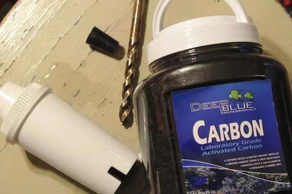
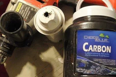
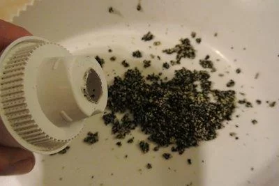
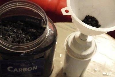
- brita filter http://www.adafruit.com/products/998?gclid=CIizqL…
- perilite http://www.adafruit.com/products/998?gclid=CIizqL…
- water pump http://www.adafruit.com/products/998?gclid=CIizqL…
- air pump http://www.adafruit.com/products/998?gclid=CIizqL…
- tubing for air pump http://www.adafruit.com/products/998?gclid=CIizqL…
- tubing for water pump (2) http://www.adafruit.com/products/998?gclid=CIizqL…
- CFL light bulbs http://www.adafruit.com/products/998?gclid=CIizqL…
- electrical wire (2) http://www.adafruit.com/products/998?gclid=CIizqL…
- glass dropper bottle http://www.adafruit.com/products/998?gclid=CIizqL…
- zip it wall board anchor (2) http://www.adafruit.com/products/998?gclid=CIizqL…
- 5 volt DC stepper motor with driver board http://www.adafruit.com/products/998?gclid=CIizqL…
- net pots (10 pack) http://www.adafruit.com/products/998?gclid=CIizqL…
- plants (6) http://www.adafruit.com/products/998?gclid=CIizqL…
- tetra – neon (5) http://www.adafruit.com/products/998?gclid=CIizqL…
- fish food http://www.adafruit.com/products/998?gclid=CIizqL…
- 15 Amp outlet http://www.adafruit.com/products/998?gclid=CIizqL…
- adehesive Velcro http://www.adafruit.com/products/998?gclid=CIizqL…
- wirenuts (bag of 25) http://www.adafruit.com/products/998?gclid=CIizqL…
- usb outlet (2) http://www.adafruit.com/products/998?gclid=CIizqL…
- pH circuit for Arduino http://www.adafruit.com/products/998?gclid=CIizqL…
- Aquarium Hydroponic PH controller meter Electrode Probe BNC Connectorhttp://www.adafruit.com/products/998?gclid=CIizqL…
- BNC Connector – Right Angle http://www.adafruit.com/products/998?gclid=CIizqL…
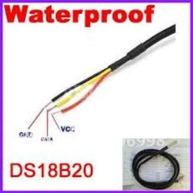
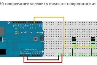
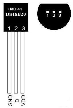
- One Wire Digital Temperature Sensor – DS18B20http://www.adafruit.com/products/998?gclid=CIizqL…
- 365buying DS18B20 Temperature Sensor – Waterproof Digital Thermal Probe Sensor DS18B20 http://www.adafruit.com/products/998?gclid=CIizqL…
- AC power plug http://www.adafruit.com/products/998?gclid=CIizqL…
- 4 wire (8 feet) AWG 18 http://www.adafruit.com/products/998?gclid=CIizqL…
- water conditioner http://www.adafruit.com/products/998?gclid=CIizqL…
- Cutequeen 30cm LED Car Flexible Waterproof Light Strip White (pack of 4)http://www.adafruit.com/products/998?gclid=CIizqL…
- LCD 16×2 http://www.adafruit.com/products/998?gclid=CIizqL…
- Electrical Red Black RL1-3 3 Pin SPST Rocker Switchhttp://www.adafruit.com/products/998?gclid=CIizqL…
- 2×4 lumber http://www.adafruit.com/products/998?gclid=CIizqL…
Step 2: Schematic of System
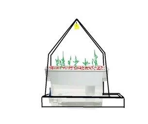
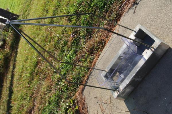
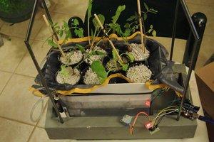
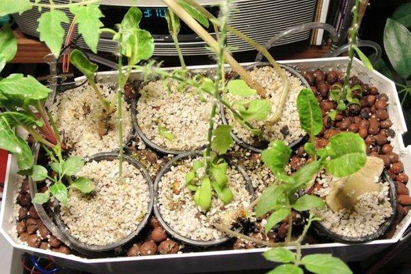
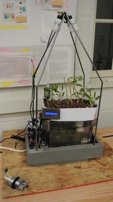
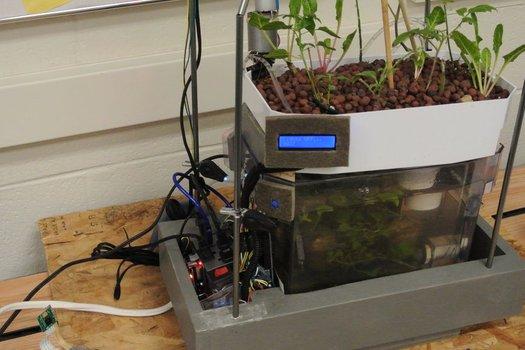
Step 3: System Skeleton
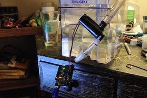
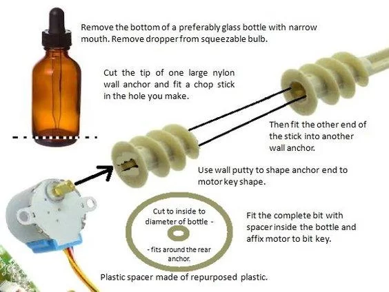
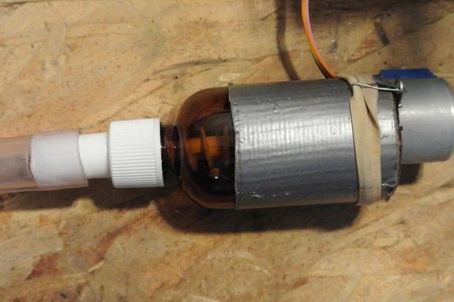
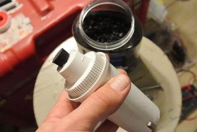
Step 4: Automatic Fish Feeder
How a step motor works: http://en.wikipedia.org/wiki/File:StepperMotor.gif
The 5V stepper motor (Fish Feeder) has (4) pins wired to a different Arduino pin. Then electromagnets are wired off set: (10,12,11,13) and when they are individually called in the program, which defines how many steps are to be taken, the electromagnets are energized and attract the gears teeth for the amount of steps defined. Our stepper is set to -1500 steps to cause a counter clockwise motion of the plastic auger bit inside the feeder. If the number was positive, it would go clockwise.
Step 5: System Power Distribution
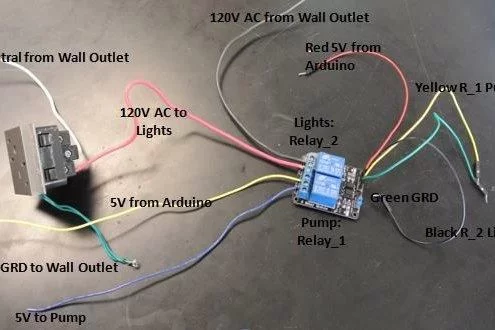

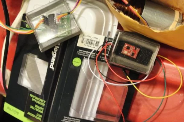
Relay_1 and Relay_2 use 5V from Arduino (small red jumper) to energize coils and close the normally open single pole relays. Relay_1 or Relay_2 (depending on code calls) are closed to allow either 5V DC to reach the Water Pump or 120V AC to reach the lights through the first outlet. Both can be on at the same time but except for testing we chose to turn the light out when pumping water. The Air Pump outlet (not shown wired) is the second outlet and is seperately pig-tailed to the 120V AC before the relays and therefore is always on.
The (2) USB ports (not shown in above image) are also pig-tailed to the 120V AC and Neutral from the Wall Outlet (no ground) before the relays and therefore output a constant 5V from USBs to power shield and Arduino.
We ended up having to add a battery pack to the circuit. If you build the system without the Pi you don’t need to worry about this. We had originally had the Pi and Arduino connected so that they were powered by each other, but they used too much power and we ran into some issues because of it. By plugging the Pi directly into the wall for power and adding an auxiliary power pack for the Arduino, we were able to make it all work.
Step 6: System Power Distribution Continued
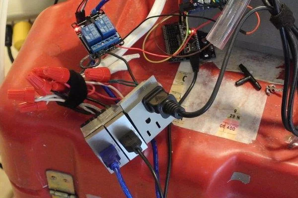
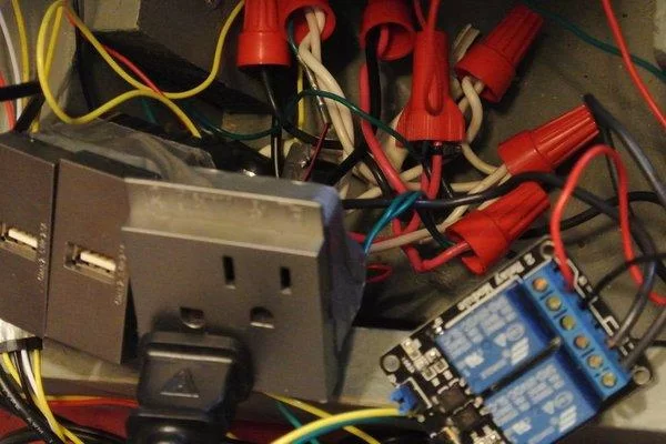
(2) USB outlets were pig-tailed before the relay for a steady 5V to power Arduino and power shield.
These 3 outlets are powered by (1) 120 volt AC power cord.
Step 7: Lights
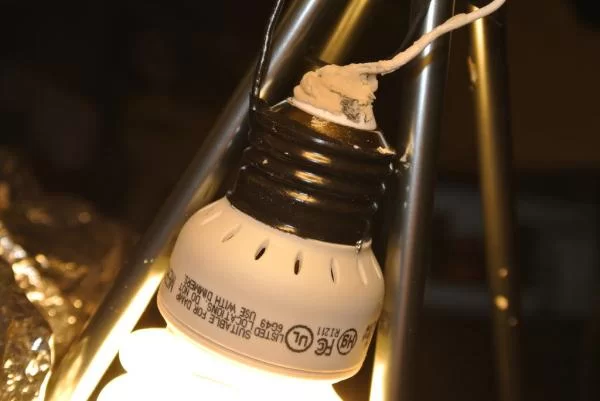
Powered by 120 volts AC and are controlled by the Arduino via relay. The positive tip of the CFL bulb was pried off and the “hot” wire was soldered to the positive wire of the bulb and covered with epoxy. The negative wire was soldered to a small hole punched into the threads of the bulb and then covered with electric tape.
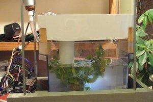
Step 8: Filtration System


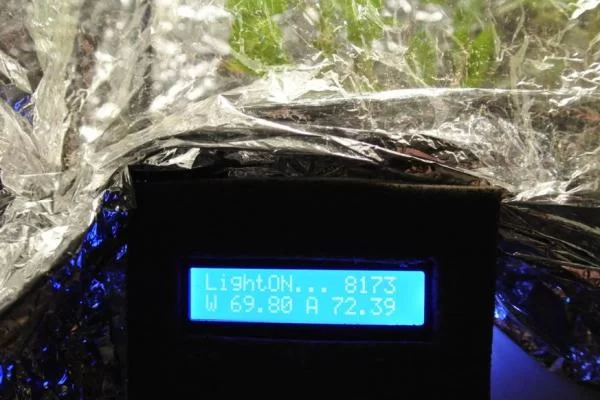
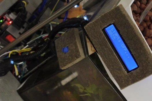
Step 9: Liquid Crystal Display
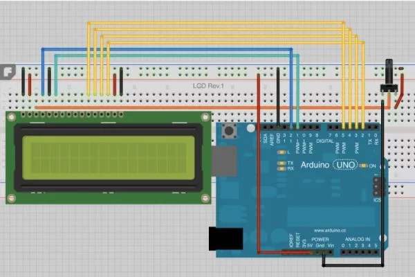
The LCD is powered by 5V from the Arduino and an additional 3.3V for the backlighting. All sensor output (air and water temperature) is displayed on the LCD, unit testing, including time between cycles, and a startup display which scrolls the team members’ names.
LCD how to: http://www.fibidi.com/arduino-lcd-16×2-characters/

Step 10: Splash Shield
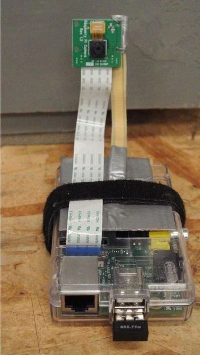
Step 11: Raspberry Pi Camera @hydroFishAqua82
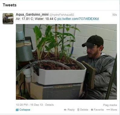
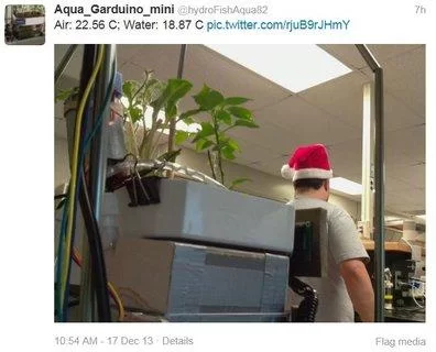
Step 12: Water and Air Temperature
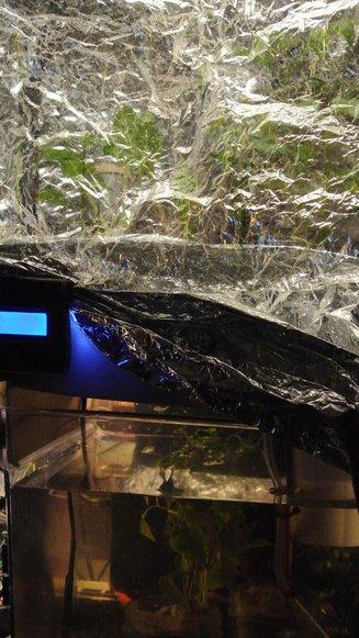
Step 13: Final Look
Step 14: Future Garduino Adventures
If we had more time, there are several things that we would’ve liked to incorporate. We hoped to get wi-fi on our raspberry pi, but we had absolutely no success setting up the dongle we had. It would be a nice thing to add in the future, but for the time we had to work it made more sense to leave it wired. It would also be nice to see the plants actually grow and flourish in this environment, but that will take time. We would like to find an economical way to check water clarity. We had also discussed a way of checking water level, but we never implemented that, and it could be useful in the future. We were never able to attach a fish powered automated espresso machine to the side, which is probably the biggest disappointment. Maybe someday.
Source: Aqua Garduino Mini @hydroFishAqua82
About The Author
Hassan Zaka
I am an expert in accounting and possess diverse experience in technical writing. I have written for various industries on topics such as finance, business, and technology. My writing style is clear and simple, and I utilize infographics and diagrams to make my writing more engaging. I can be a valuable asset to any organization in need of technical writing services.
Follow Us:LinkedinTwitter