This instructable will cover the building process of an Arduino 4x4x4 LED Cube. I will be using an Arduino to control the LEDs. Since the Arduino (Freeduino) has a total of 20 pins (including the analog pins) we will not need to have any multiplexing or shift registers. I will take you though what i did in order to build the cube and create some designs of your own.
Step 1: Bill of Materials
Bill of Materials
For this project I used the freeduino Arduino. Because the Freeduino has a total of 20 I/O pins (with using the analog pins) we will not need and multiplexing or shift registers. So all we will need for our project is:
1. LED x 64
2. Resistors x 16
3. Arduino x 1
4. Perforated PCB
5. Soldering Iron
6. Drill (for the jig)
7. Piece of wood (for a jig)
Vendors:
I have found sparkfun.com and digikey.com to be good suppliers of small electronic components in general and are currently the only two that I have purchased anything from.
Step 2: Choosing LED
LED Type:
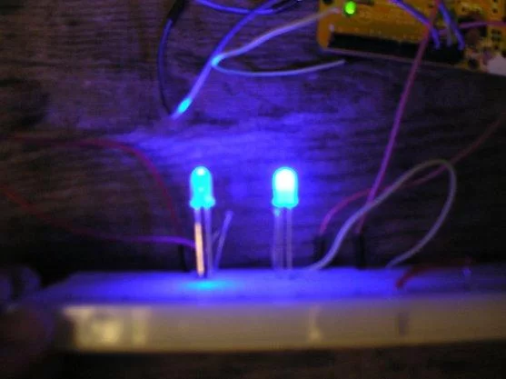
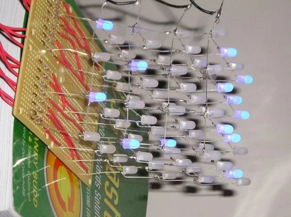
LED’s come in different shapes, sizes and colors. For this project we will need diffused through hole LED’s. When an LED is diffused is disperses the light in all directions rather than mainly toward the top of the LED. By using diffused LED we will have get good color out of our LED’s from the side of the cube. Since we will only have a cube that is 4 LED deep I chose to use 5mm super bright LED’s from Sparkfun. 3mm LED’s will work just fine for this small of cube the fall back from brighter LED is when you have a large cube and cannot view the LED’s in the center.
The LED’s I ordered were not diffused this is not that big of problem all you need is some sand paper (a dremel is faster) to sand each LED will light up all parts rather than the focal point at the top.
Test your LED’s:
I would recommend that you test each LED in a bread board before soldering. Simply use the +5v and connect that to a resistor (size discussed later) and to the LED just to make sure each LED lights up it would be bad to build the cube with a faulty LED in the middle somewhere.
LED Layout:
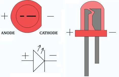
Most LEDs positive pin (anode) is the longer pin coming out of the LED and the negative (cathode) is the shorter pin. You can also look at the little metal inside the smaller metal piece is the positive end (anode) of the LED.
Step 3: Choosing the Resistors:
Step 4: General LED Cube Information
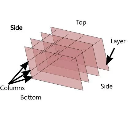
The cube I am constructing will be a 4x4x4 in other words it will contain 64 LED’s with 16 columns and 4 layers. Each column will be the LED’s positive pins connected together allowing 5 volts to pass to all the LED’s in that column. The Layers will consist of the LED’s negative pins connected together To control the LED’s we will be able to supply 5 volts to the column and let the layer connection go to ground. In order to prevent a column from drawing to much current there should only be one layer on at a time.
How do we light up the entire cube at once you ask? Well, we will use something call persistence of vision. An LED leaves an afterimage in the human eye, in other words even when the LED is turned off for a fraction of a second our brain perceives the LED as still light up.
Using this we can control each LED in the cube with only a total of 20 I/O from our arduino. For example if we want to light the third LED on the fourth column we will simply set the output to that column to HIGH (5 V) and the output for that layer to LOW (0 V) thus creating a ground and allowing current to flow and the LED lighting up.
Step 5: Constructing the Jig
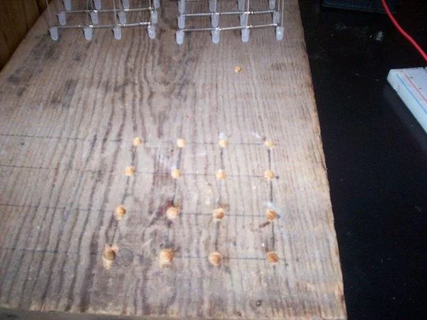
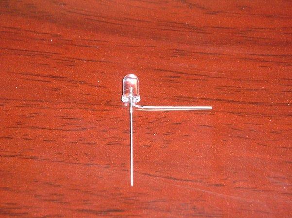
To determine the size of your cube you will need to measure the bent cathode portion of the LED. My bent LED turned out to be about 25 mm therefore I drilled my holes roughly 23 mm apart to allow me 2 mm in order to solder the cathodes together.
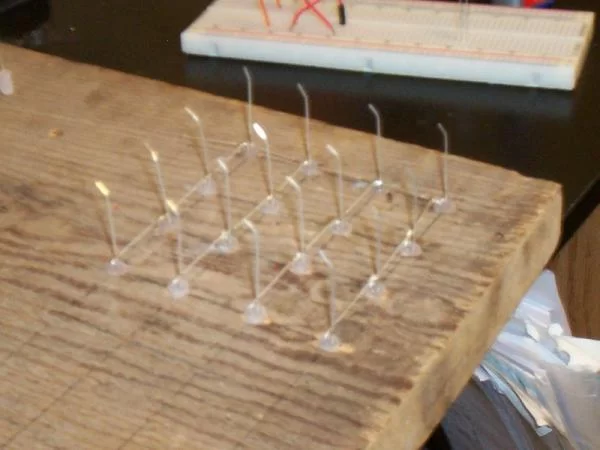
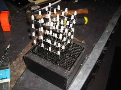
Step 6: Constructing the Cube Layers
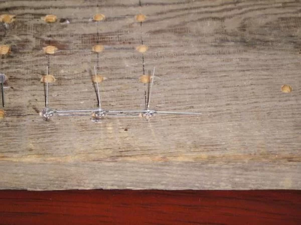
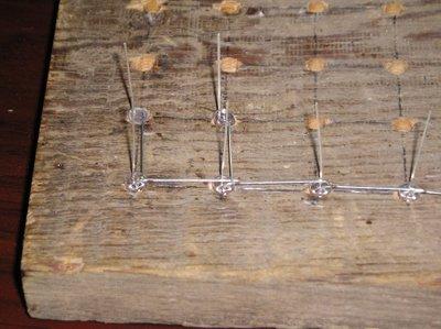
To start we will have one LED whos negative pin will go outside the cube. Next start placing LEDs and soldering as you go I recommended that you complete the row where the pin is sticking out. Then solder up the other rows to that main row.
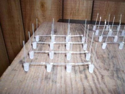
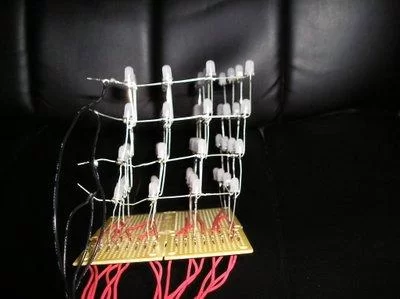
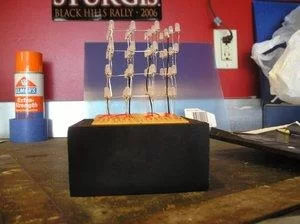
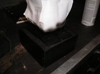
Step 7: Constructing the Cube
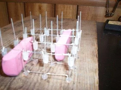
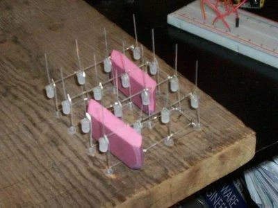
To hold up the Cube while i soldered I used erasers that i cut to the correct size.
Simply continue this step until all of the layers are soldered together.
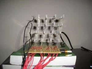
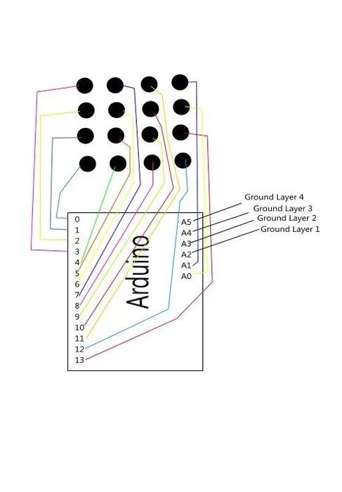
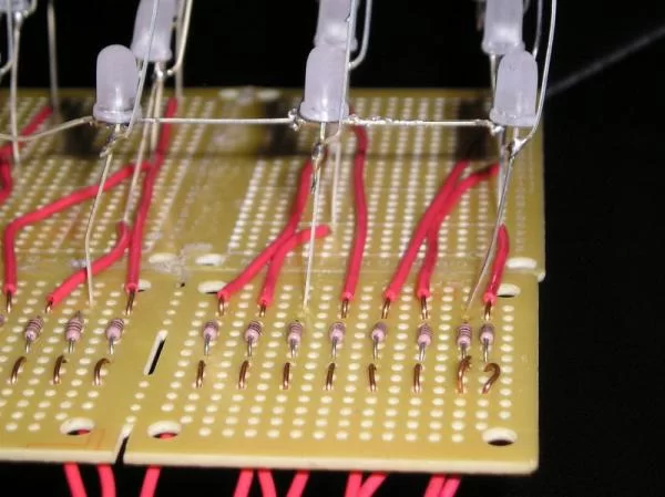
Step 8: Connection
Step 9: Base and Soldering Resistors:
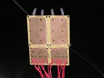
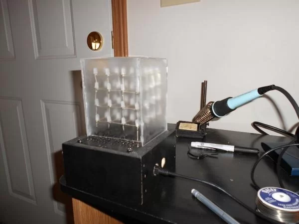
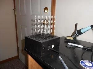
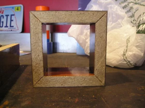
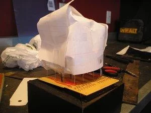
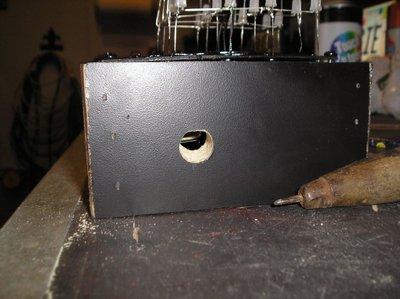
Step 10: Base/Box

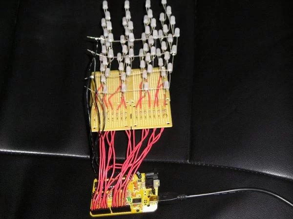
Step 11: Programming:

Programming can take some time some tutorials have good condensed code that is easier to do designs but again for time reasons i was not able to spend much time doing that. However I was able to do some designs and looking at them will let you better understand what is going on. I provided my code at the bottom (its kinda sloppy)!
The ground/negative/layer pins:
Remember the Persistence of Vision since we want to be careful to only have one layer on at a time (although I have made the mistake and am pretty sure the arduino can handle it but why try and break things?). Since the layers are ground they are backwards from the column pins. When we want to ground a layer we set the pin in the code to LOW. This creates a difference in potential allowing current to pass and the LED to be lit up. When we set the ground pins to HIGH no there is no potential difference and the LED’s do not light up.
The Column/Positive pins:
To control the column pins we can set the pin number to HIGH thus allowing 5 V to flow out of the pin. So when a specific layer has been grounded the 5 V will flow and the LED on that column and layer will be lit up! If we do not want a LED on that column to be lit up when a layer is grounded we can set that column to LOW and the LED will not light up.
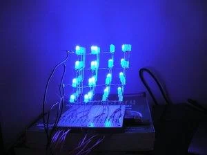
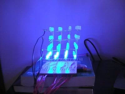
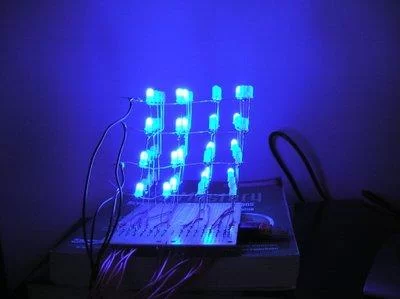
Here is a video of my cube in action! The acrylic box turned out a little hazy but I removed it in the second half of the video so you can see how it looks both ways!
Thanks for reading!
source: Arduino 4x4x4 LED Cube
About The Author
Hassan Zaka
I am an expert in accounting and possess diverse experience in technical writing. I have written for various industries on topics such as finance, business, and technology. My writing style is clear and simple, and I utilize infographics and diagrams to make my writing more engaging. I can be a valuable asset to any organization in need of technical writing services.
Follow Us:LinkedinTwitter