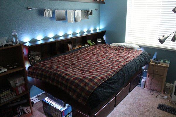
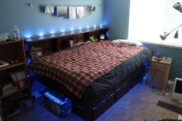
Hi All! I have wanted to do something fun with my bedroom for a while now and the Make it Glow challenge provided me with a reason to do so. A few months ago I acquired a strand of GE-35 Color Effects lights and owing to the inherent dangers of controlling wall voltages, the strand provided me with an alternate and safe way to light up my room and be able to control it with my arduino. As I researched the hacks for the RGB strand I was taken with the idea of having the lights move with my music. I ordered a MSGEQ7 from Sparkfun and started my room’s renovation when it arrived in the mail.
Step 1: Materials Needed

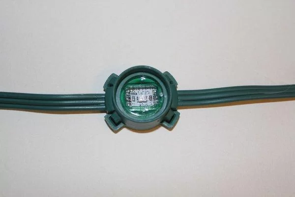
1x GE- 35 Color Effects Light Strand- I used a 50 count strand
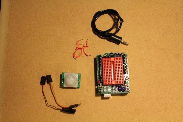
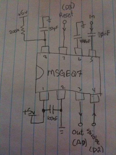
1x MSGEQ7
1x 10nf Cap
2x 100nf Cap
1x 200K resistor
1x Wire
1x Breadboard – I used a Proto Shield
1x LED – I used a red LED
1x PIR Sensor – Radio Shack
1x 3″ Servo Extender
1x Male to Male Audio Cable- Cut in half and each end terminated in a pin Header
1x Stereo Audio Splitter
1x Music Device
1x Pliers- For pesky staples
1x Mono Plug
Staple Gun
Hot Glue Gun
Soldering Iron
Solder
Optional- Knife
Optional- Drill
Optional- Hammer
Optional- Scroll Saw
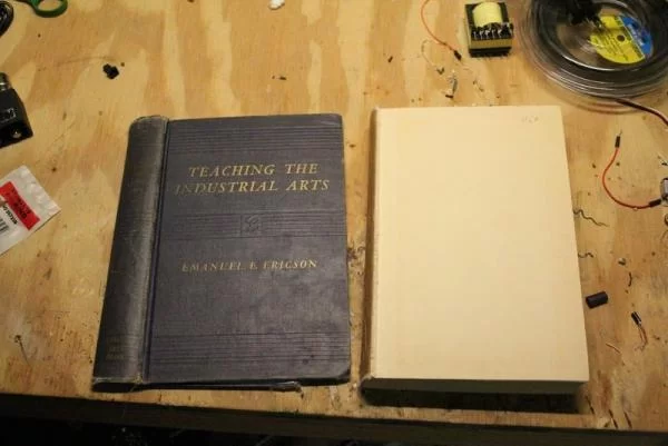
Optional- Book- One you don’t mind ruining forever
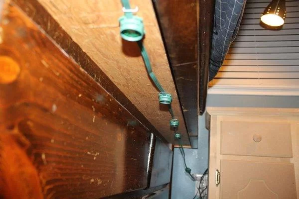
Step 2: Hacking the GE- 35 Lights
Step 3: Stapling Up the Strand
Step 4: Wiring Up the MSGEQ7 Chip
Step 5: Attach PIR Sensor
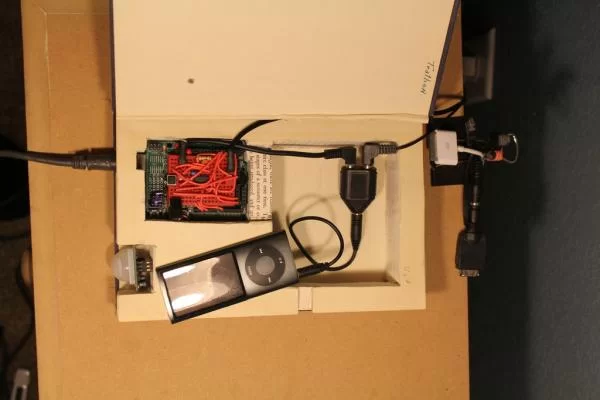
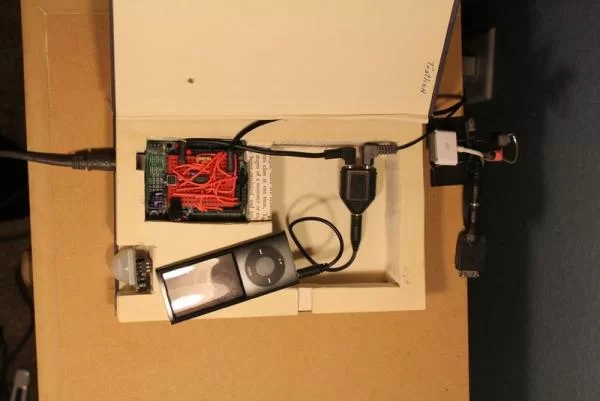
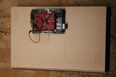
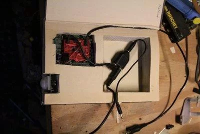
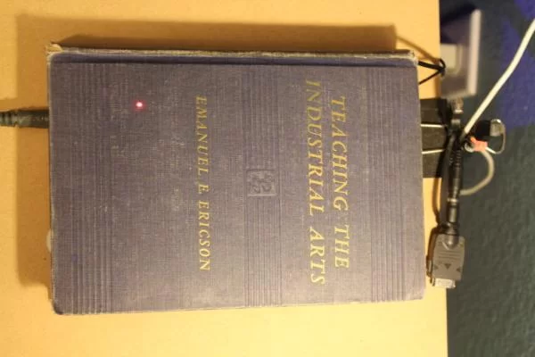
Step 6: Optional- Secret Book Compartment
Step 7: Programming
This is the most time consuming part of the whole build. I admittedly didn’t write all of the code but most of it is mine. I stole parts of the example code on this site as well as some of the example code from austinlightguy’s website and the doityourselfchristmas website (I couldn’t find the thread as the site is down right now). The rest of the code is 100% me and as such may be a bit convoluted. If you have any questions feel free to ask me. It currently has an auto off feature so the lights turn off after 15 minutes of no movement and a “reset” feature so if there is no movement detected for 20 minutes the function will change to white so when I walk in the room, I will be able to see. It has three functions, cycled through with the button, All white, All off, and color organ mode. Right now the color organ is simply blue but feel free to change it to be more interesting. When the PIR detects motion the red LED lights until the motion stops, I used it mostly for debugging but it is still a nice feature to have.
-Updated Code-
I got rid of the straight blue music visualizer in favor of mapping each channel to a different color (r g b) on the top of my bed and the bottom of my bed. Basically the “treble” frequencies are on the top of my bed and the “base” frequencies on the bottom. I also added a color changing visualizer for just one frequency on the top half of my bed. I will work on implementing the bottom here soon. I also added just a straight color cycling function that fades through almost all the possible colors. Finally I worked out some timing issues with the auto off functions.
-Updated Code 12-1-2012
More improvements in the coding and functions. Designed and etched a custom board for the lights and stuffed it all into a radio shack box. There are provisions for two buttons in the code but I have yet to implement functions for the second button. I also took out the PIR functions but the custom board has a place for a PIR sensor and it wasn’t too hard to add that functionality. BRD and SCH files to come soon.
Step 8: Completed V1 Project
Step 9: V1.2 Project
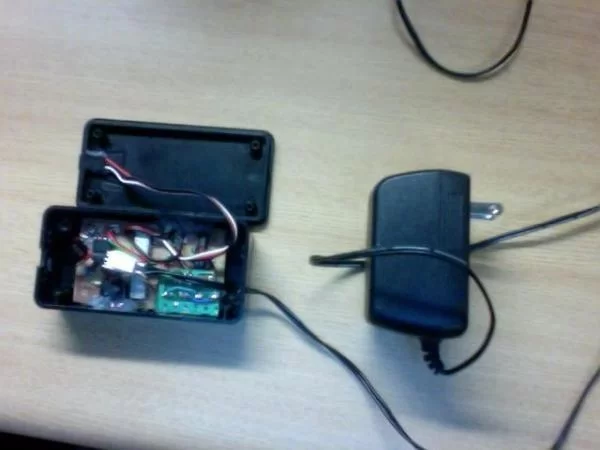
I had some time over summer so I went ahead and made a board for my circuit and made it a little nicer than the jumble of wires on top of the protoshield. I added the 4066 chip in the schematic so that I could interface with a cheap push button iPod controller but I never got around to actually implementing that part. My eagle design skills at the point that I made this board were somewhat lacking but the circuit does work, just make sure to use a steady 5v power supply with the controller. All of the connectors are headers in the schematic as I was mounting it in a box and wasn’t sure where I was going to put things so I just soldered wires to the audio jack and buttons and such and then hot glued it all into the case. Its not pretty but as I said before it does work. There is some code for the board below. If you have any questions about this version, feel free to ask.
Step 10: V2 Project
Currently I am working on a project for a DJ friend of mine which will consist of 3 boxes. Unfortunantly we could not afford individually addressable LEDs and so each box will only be able to be one color at a time. They will be individually controlled by an MSGEQ7 and an integrated Atmega328 with the arduino boot-loader sending out PWM to N-channel Mosfets. I am using an RGB LED strip ordered from China, cut into 3 parts, one for each box. There will be a central controller with 4 wires going to each box, one for common power and 3 for Red, Green, and Blue control. Basically, to turn on a color, that colors wire is grounded which completes the circuit and turns on the LED.See http://learn.adafruit.com/rgb-led-strips for more information on how the strips work. More info to come as this project progresses into its final stages.
Source: Extreme Color Organ
About The Author
Hassan Zaka
I am an expert in accounting and possess diverse experience in technical writing. I have written for various industries on topics such as finance, business, and technology. My writing style is clear and simple, and I utilize infographics and diagrams to make my writing more engaging. I can be a valuable asset to any organization in need of technical writing services.
Follow Us:LinkedinTwitter