Hey guys! I’d like to share with you the input device I created specifically to interact with AR glasses like the Google Glass, Meta, Moverio BT or with the VR headsets like Oculus Rift, Samsung Gear VR, vrAse, Durovis Dive. Those new products are amazing and they need new types of input devices. This instructable will describe how to build your own “Gravity Touch bluetooth glove” and I will also give you some tips to build your own Durovis DiveVR headset so that you will be able to enjoy full mobile VR. Because this glove will be of most use for VR game, I have created a Unity3D plugin for Android that handle the communication between your app and the glove. It means that you will be able to use your Gravity Touch glove to interact with your Unity3D VR game. The Arduino code and the Java class I wrote to handle the communication between the glove and the Android device will also be available so that you will be able to adapt them for your need.
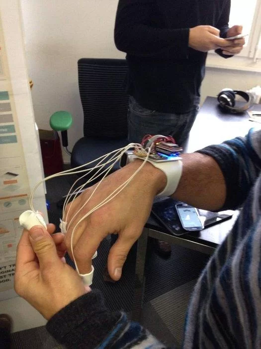
The prototype of the glove described here will be providing the following data wirelessly:
- the orientation in space of the user’s wrist thanks to the FreeIMU board.
- the pressure applied on every user’s fingertip.
The glove communicate through bluetooth with either a smartphone Android or a computer (not reviewed here). Take a look at the video to have an overview of its functionalities and possible uses.
This instructable can also be useful for you if you want to create an Arduino system that must communicate through bluetooth with you Android phone/tablet, if you want to acquire touch input with your Arduino or if you want to use the FreeIMU device wirelessly.
Step 1: Glove: Preparation
Electronic parts you will need:
- Arduino micro
- FreeIMU 10 DOF (3 x gyro + 3 x acc + 3 x magneto + 1 x pressure sensor)
- Bluetooth Mate Silver from sparkfun
- 5x Force Sensitive Resistor
- 9V Battery and its Snap connector
- 3m of flexible soft electric wire about 0.2mm² (-> diameter 0.5mm). I took 4 different colors.
- 5x 10kΩ metal film resistor (like this)
- A soldering board (like this)
Materials used to build the glove (link for illustration purpose only, you should be able to find all the stuff below in your hardware shop):
- PVC foam sheet 2mm thick (like this) to make the bracelet.
- 1mm thick cardboard, dim: 50 x 46 mm to have a solid base for the electronic parts.
- velcro tapes with velcro on one side and glue the other side (like this)
- two sided tape 2mm thick (like this)
- elastic band 10mm large (like this)
- staples
Tools:
- Soldering iron
- Scissors
- wire cutter
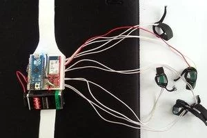
The glove will be composed by a bracelet with a cardboard platform that will serve as the base for the electronics part and the five fingertips touch sensors (or less if it fits better your need). On the top of the bracelet’s platform we will construct two layers of electronic parts. On the first layer, we will put the FreeIMU along with the 5 metal film 10kΩ resistors. The second layer will contain the Bluetooth module as well as the Arduino micro. The battery will be attached to the bracelet with a velcro tape.
Let’s start by crafting the bracelet.
Step 2: Making the Base Structure: the Bracelet
The bracelet will be the base structure where we are going to put all the electronic components.
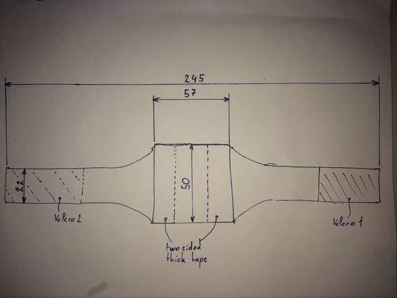
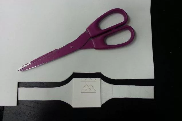
Take the PVC foam sheet and draw on it with a pencil the shape of the bracelet as illustrated on the schematic below (dimension in millimeter). Grab the scissors and cut the foam by following the line.
Once you have your bracelet ready, cut a rectangle 57 x 50mm in the cardboard, it will be used as the solid base for the electronic parts.
Now we are going to fix the cardboard on the bracelet. Cut two pieces 50mm length of the two sided thick tape and paste them on the cardboard (see schematic). Then fix the cardboard on the bracelet.
Cut then 45mm of the velcro tape and paste it on the bracelet as illustrated on the schematic above.
Step 3: Overview of the Electrical Schematic
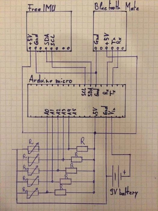
Before starting to solder, let’s take a look at the electric schematic shown above. As you can see, the schematic is pretty simple.
Power: the Arduino is powered by the 9V battery through its Vin pin. We take advantage of the Arduino’s internal 5V converter to provide the 5V power to the FreeIMU and bluetooth boards by connecting there 5V pin to the 5V output pin of the Arduino. For more information about the min and max input voltage the Arduino can handle, please check the Arduino’s documentation.
Arduino – Bluetooth Mate communication: the bluetooth module from Sparkfun comunicate with the Arduino through its serial port (Tx/Rx). The Tx pin of the Arduino must be connected to the Rx pin of the Bleutooth module and the Rx pin of the Arduino must be connected to the Tx pin of the bluetooth module. If you want more information about how the Bluetooth Mate Silver module works, check its description on the Sparkfun website.
Arduino – FreeIMU communication: the FreeIMU v0.4 communicate with the Arduino with the I²C (TWI) protocol. The pin used are SDA and SCL. The SDA pin (pin 2) of the Arduino is connected to the SDA pin of the FreeIMU and the SCL pin (pin 3) of the Arduino is connected to the SCL pin of the FreeIMU. WARNING, the FreeIMU SDA and SCL ports work in 3.3V while the Arduino’s one would normally work in 5V but thanks to the pull up internal resistors of the Arduino micro, the communication is possible without extra adaptation.
Touch detection: the touch detection system is as simple as a voltage divider. I use the fact that the resistance value of the Force Sensitive Resistor decrease at the same time the pressure applied on it increase. This variation of resistance will induce a variation of voltage across the Rv and this is what we measure with the analog to digital converter of the Arduino (pin A0-A5). The resistance range of the Force Sensitive Resistor goes from 1MΩ (no pressure) to 2.5kΩ (full pressure applied). As the current driven across the five voltage divider is delivered by the 5V pin of the Arduino, I don’t want to drive more than 500uA for each voltage divider which means that R + Rv when Rv is minimum must be equals to 10kΩ. As Rv min = 2.5kΩ => R = 7.5kΩ. This explain the choice of a value of 10kΩ for R (the closest value would be 8.2kΩ, I took the closest value I had in my lab 😉 ). The voltage values across Rv recorded by the Arduino will go from 5V when no pressure is applied to 1V under full pressure.
Step 4: First Layer: FreeIMU + Resistors Board
As I said earlier, the electronic parts will be separated into two superimposed layers. Let’s make first the bottom layer where we will put the FreeIMU boards as well as the five 10kΩ resistors board.
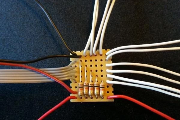
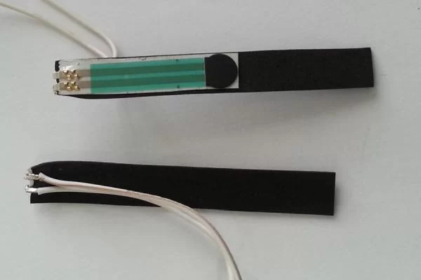
10kΩ resistors board
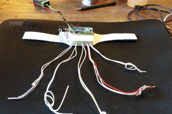
The resistors board is shown above. The white wires make the connection to and from the fingertips touch devices. The black wires are Gnd and the red ones the 5V. The five wires gray flat cable will be connected to the Arduino’s pin A0 to A4. Note: we don’t need the upper red wire at the left bottom of the board on the first image.
Take the soldering board and cut it so that you end up with a piece containing at least 9 track with 7 holes (see images).
Solder the five resistors as shown in the image 1 and 2.
Cut 10 pieces of wire that must be long enough to go from your wrist to your finger tips (white wires on the image). I recommend to make it longer (35 cm) so that you can cut them at the good length afterwards when we will create the fingertips touch devices. Solder this wires as shown on the image.
Cut 2 pieces of red wires and 2 pieces of black wire 12 cm long. solder them as shown on the image.
Cut either 5 independent wires or a 5 wires flat cable (like the grey cable on the picture) 12 cm long. Solder them.
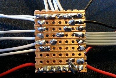
Compare your board with the front and back image of the board above to be sure that everything looks good.
FreeIMU board
Solder the red and black wires that come from the resistors board on the FreeIMU board as shown on the image 3.
Cut two wires with different colors with a length of 12 cm. Solder them on the FreeIMU board as shown. Those two wires will be connected to the Arduino’s I2C port (SDA and SCL pins).
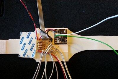
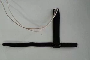
Attaching the boards to the bracelet
Use the two sided thick tape to fix the two boards on the cardboard. Cut new piece of cardboard with the same dimension as before (50 x 57 mm) to serve as base for the second layer. Build a frame between the two layer with the two sided thick tape so that the 10 long wires go out from the first layer as shown in image 3, 4, and 5. Once the frame is thick enough around 1.5cm, you can paste the floor of the second floor (image 4 and 5).
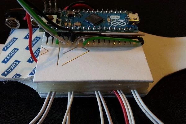
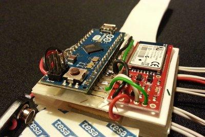
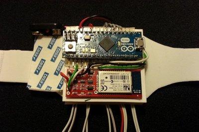
Step 5: Second Layer: Arduino Micro + Bluetooth Module
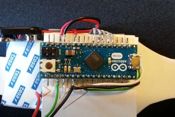
Unfortunately, the Arduino micro is not available without the breadboard pins. To gain some height and to fix the Arduino on the bracelet, I folded the pins as shown on image 1. The best way to do it is folding every pin one by one with a small nose plier. Be careful to not break the pin. Once every pin is folded by 90° we can start soldering the wires on them as following:
9V batery wires:
- Red (+9V) to Arduino pin Vin
- Black (Gnd) to Arduino pin Gnd
Fisrt layer 5V power wires:
- Red wire from the first layer to Arduino pin 5V
- Black wire from the first layer to Arduino Gnd pin (as we have 3 Gnd wires to connect to 2 Arduino Gnd pin, you will need to attach 2 Gnd wires in the same pin. See image 1).
Flat cable:
- A0: index
- A1: middle finger
- A2: ring finger
- A3: pinky
- A4: thumb
I2C (PWI):
- Green wire from first layer to Arduino SCL (pin 3)
- White wire from the first layer to Arduino SDA (pin 2)
Bluetooth module:
- 5V: Red wire from first layer to Bluetooth 5V hole.
- Gnd: Black wire from Arduino Gnd pin to Bluetooth Gnd hole
- Rx: White wire from Arduino Rx pin to Bluetooth Tx hole
- Tx: Green wire from Arduino Tx pin to Bluetooth Rx hole
See the images to have a visual control of what you are doing.
When everything looks good, paste the Arduino and Bluetooth module on the second floor with the thick double sided tape.
Step 6: Crafting the Fingertips Touch Devices
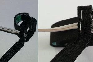
The fingertip touch device is basically a resistor that changes its value when you press on it. The sensitive area of those resistors is the black dot that fits perfectly the fingertip. The goal here is to embed the resistor in such a way that the sensitive area will always be in contact with your fingertip. To make a single fingertip touch device we will need:
- 1 force sensitive resistor
- thin double sided tape
- PVC foam, either the same as the one used to make the bracelet or a thiner one if you think it’s too thick (in the images I took a 1mm thick black PVC foam).
- two staplers
Cut the PVC foam in rectangle 9 x 90mm. Paste the resistor with the thin double sided tape as shown on image 1. Bend softly the two resistor’s pins so that you can solder the wires coming from the bracelet on the opposite side as shown on image 2. Before actually soldering the wires, we must cut them at the appropriate length. To do so attach the bracelet to your wrist and estimate the length of the pair of wire (two wire per finger) for every finger. Be careful, you’ll need to be able to form a fist while bending the wrist downward. Here is a reminder of what wire go with what finger. A0: index, A1: middle finger, A2: ring finger, A3: pinky, A4: thumb.
Once all the wires are cut, solder them to the pin of the resistor as in image 2.
Cut 60mm of the elastic band and attach it to the PVC band with a stapler as in image 2. The PVC foam band is folded around the elastic band. It means that the stapler will go across 3 layers (PVC – elastic – PVC).
Form a loop with the elastic band and put another stapler an top of the other end of the PVC band where the pins of the resistor are. The layers inside the stapler are elastic – PVC – resistor – elastic (beginning from te inside of the loop). BE CAREFUL TO NOT STICK THE STAPLER INSIDE THE RESISTOR otherwise you’ll risk to create a shortcut. The result should look like image 3 and 4.
At this point, the hardware is ready. Now let’s dig into some code to make the magic happen.
Step 7: Testing and Calibrating the FreeIMU
FreeIMU is an Open Hardware framework for orientation and motion sensing. The communication with the FreeIMU bard is handled by the FreeIMU library for Arduino. Check out the official website to download the last version of the library and for a detailed setup and installation instructions.http://www.varesano.net/projects/hardware/FreeIMU
Here is the step to be up and running:
- Download the FreeIMU Arduino library.
- Setup your Arduino environment as explained in the Additional Arduino Libraries section of Arduino’s documentation.
- Calibrate your FreeIMU board with the help of the calibration tool provided by the FreeIMU team. The result of the calibration process will be a file: “calibration.h” needed to obtain stable orientation measurement from the FreeIMU.
Once you have downloaded the library, follow the Additional Arduino Libraries guide to setup your Arduino environment. Choose the manual installation so that you will have a better understanding of the folder structure of the Arduino environnement.
Testing the FreeIMU:
Connect the Arduino micro to your computer.
Launch the Arduino Editor program and open the “FreeIMU serial” sketch under “File -> Examples -> FreeIMU -> FreeIMU_serial”.
Select the board Leonardo under Tools -> Board.
Select the serial port on which the Arduino micro is connected (Tools -> Serial Port) and write down the name of the port (Windows something like COM2, Mac something like /dev/tty.usbmodem1421).
Upload the sketch to the Arduino micro.
To make a quick test to check that the Arduino responds, open the Serial Monitor (Tools -> Serial Monitor), check that the properties of the communication are “Newline” ans “115200 Baud”. Put v in the input field and press “Send” button. If everything is ok, the Arduino will send you back:
FreeIMU library by Fabio Varesano - varesano.net, FREQ:16 MHz, LIB_VERSION: DEV, IMU: FreeIMU v0.4
You can play with others commands to see the response of the Arduino micro (check the code the available command).
The application that comes along with the FreeIMU library to test if your FreeIMU is working properly is “FreeIMU_cube.pde”. This is a Processing sketch, so you will need to download Processing to run it. The GUI of processing is really similar to the Arduino Editor. Open “FreeIMU_cube.pde” with processing, it is located under: “FreeIMU-20121122_1126/processing/FreeIMU_cube/FreeIMU_cube.pde”. We need to tell the program on which port the Arduino micro is attached to. To do so find the code written below in the Processing’s code:
final String serialPort = "/dev/ttyUSB9"; // replace this with your serial port. On windows you will need something like "COM1".
Replace “/dev/ttyUSB9” by the serial port name you wrote down before (the port name the Arduino micro is attached to).
Run the program, if everything goes well you should see a Window with a 3D cube on it. The cube represent your FreeIMU so when you move your FreeIMU, the cube should follow the mouvement. If it is not the case, don’t panic! We must calibrate the FreeIMU.
If you get some errors or if the program doesn’t start (just a void window), try to reset your Arduino micro and relaunch the program. If it doesn’t work please check the troubleshooting section on the FreeIMU website.
Calibrating the FreeIMU:
Download the Calibration Tool (only available for PC and linux) and follow the instructions to obtain your calibration file “calibration.h”. Once you have this file, copy it in the FreeIMU folder of your Arduino environnement to replace the existing one (libraries->FreIMU->calibration.h).
Try to run again the “FreeIMU_cube.pde” processing program and this time the cube should follow the orientation of the FreeIMU without any drift.
Step 8: Testing the Touch System
I will cover here how to test the Arduino code needed to acquire the touch events generated by the fingertip touch devices. As mentioned earlier, the code detects the touch events be measuring the variation of the voltage across the force sensitive resistors. I have introduces in the code a threshold value “touchThr” above which we consider the state as “NO_TOUCH” or released state and below which we consider the state as “TOUCH” or pressed state.
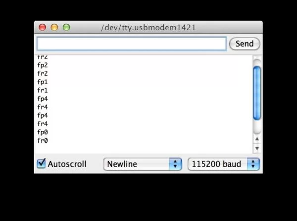
To test the sketch (Arduino code) in your Arduino micro, download the Five_Touches.zip file, unzip it and open the “Five_Touches.ino” sketch. Connect your Arduino micro to your computer and upload the sketch. Once the sketch is successfully uploaded, it will start to send the touch events generated by the fingertip touch device to the PC. To see those events open the Serial Monitor (in Arduino editor goto Tools->Serial Monitor). Select the option “New Line” and set the baud to 115200.
Now when you touch one of the fingertip touch devices, you should start seeing text appearing in the Serial Monitor (see image1). One line per event: “f” is for finger, “p” is for pressed and “r” for released, “number from 0 to 4” is for the port number A0 to A4.
So if you get “fp2” it means that finger 2 (resistor connected to port A2) has been pressed. If you get “fr0”, it means that finger 0 has been released and so on and so forth.
Step 9: Sending Touch Events to the Phone Through Bluetooth
How to give a friendly name to your Bluetooth module:
- upload “Bluetooth_cmd” sketch into your Arduino micro.
- Open the Arduino’s Serial Monitor (cmd-maj-M or Tools->SerialMonitor).
- Verify that the Serial Monitor’s parameter are:
- Newline
- baudrate: 115200
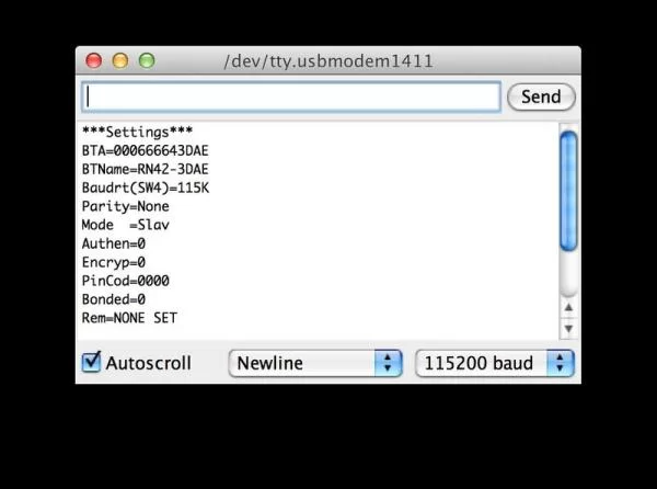
- enter “D” and press send button to get the “Basics Settings” of your bluetooth module. The result should be like in screenshot “1 – cmd D”.
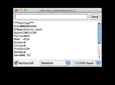
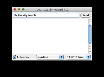
- enter “SN,The new name of your device” and press send button to set the name of your module. On the screenshot “2 – cmd SN” I changed my bluetooth module’s name as “Gravity touch”.
- enter command “D” again to see that the name pf your module changed.
You can play with the command listed on Appendix B of the datasheet of the module. When you are ready to go with your module, send the reboot command: “R,1”.
Let’s test the bluetooth communication between your Android phone and the glove.
- Download the “Gravity_Touch_Bluetooth.zip” file on your computer, unzip it and upload the code on your Arduino.
- Install the “GravityTouchTest.apk” file on your Android phone either by downloading it directly from the web into your phone or either by downloading it on your PC and then uploading it on your Android phone.
Enable the bluetooth on your phone and launch the “Gravity Touch Test” app (be sure that the Arduino is powered before launching the app). The green LED of the Bluetooth module should turn green which means that the connection between your phone and the glove is on. If everything worked fine you should see the cubes turning green on the screen when you press on the corresponding finger of the glove.
I attached the java code I wrote to handle the the Android side bluetooth communication. This code is composed by three files: MainActivity.java, GloveTouchThread.java and BluetoothNoSupportedDialod.java. I don’t review here this code, it should be pretty self explanatory if you’re an Android developer. Note: In this project I used Bluetooth standard which is more tricky to play with compared to the new Bluetooth LE (low energy). See herefor the new simplified pipeline to handle communication between Android and Bluetooth LE.
At this point, the glove sends touches and orientation info and the phone catch them. Like I said in the introduction, the aim of the Gravity Touch glove is to be an input device for VR or AR games. So what we need to do next is to forward those info to the Unity3D game engine. Why Unity3D ? Well, because it is the tool of choice when it comes to 3D games development on mobile.
Step 10: Gravity Touch Unity Plugin
If you are a Unity developer and you want to use your new Gravity Touch glove to control your Android game, you can download the Unity package “gravity_touch.unitypackage” and import it into your Unity project. Take a look at the “Test” scene to have an overview of the architecture of the SDK.
As promise, I will give you some links and tips to build your own VR mask for less than 50$. The best solution out there is probably Durovis Dive. Durovis Dive solution is composed by a VR headset open hardware called OpenDive and a SDK that allows you to track the orientation of your phone. Taken together, it will allow you to build an Oculus rift with your Smartphone!
Building the OpenDive headset:
- Follow this link, download the STL file (file used by a 3D printer to build the frame of the headset) and check out the makexyz website to find your nearest 3D printer. It cost me 35$ to have my headset printed in less than 4 days.
- The Durovis OpenDive lens kit can be bought on amazon here.
- Once you have the lens and the frame printed, follow the instruction on the Durovis Dive video “OpenDive build instruction” to put everything together.
Now that you have your glove and the VR headset ready, let’s make some cool game to use it and don’t hesitate to share them with me!
Source: Gravity Touch Bluetooth Glove
About The Author
Hassan Zaka
I am an expert in accounting and possess diverse experience in technical writing. I have written for various industries on topics such as finance, business, and technology. My writing style is clear and simple, and I utilize infographics and diagrams to make my writing more engaging. I can be a valuable asset to any organization in need of technical writing services.
Follow Us:LinkedinTwitter