A robot is a virtual or mechanical artificial agent. In practice, it is usually an electro-mechanical machine which is guided by computer or electronic programming, and is thus able to do tasks on its own (http://en.wikipedia.org/wiki/Robot). Well, today you will learn exactly how to build a Homemade Magic Lamp Card Box. Really, this is two instructables combined into one, them being:
1) How to sculpt nearly ANYTHING out of extruded polystyrene.
2) How to design and build a pneumatic mechanism and control system.
As an introverted electrical engineering student sculpting really isn’t my forte, so that took most of the time. Nearly 33 hours to get a final product! Needless to say I made up for some of that with the designing and building of the electronic control system, but it is all pretty simple, just takes a lot of time and dedication. The reason I made this was for my sister’s wedding. The theme is the magic of Disney, so like any good brother would do I set off on a journey to design and create one of the most elaborate card boxes the world has ever seen!
Let’s Get Started!
Step 1: Design & Preparation
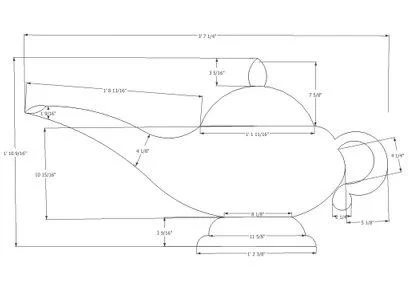
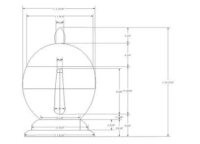
Like all good robots, they must be well designed to function properly. However, I know that everyone will be building their own robot with their own design so I won’t spend too long on this section. I just wanted to stress it’s importance by giving it it’s own step. For my project, I started from a picture of the magic lamp and created a scale drawing using Google SketchUp 8. It is a really great program for any hobbyist to learn because it’s free and there isn’t a very steep learning curve at all! I’ll post the link for the download below. After I created my scale drawing, I knew I would need a design for the electronics. I used the EAGLE software package to design a schematic for my Electronic Control Board. Next, I decided that there would be too many cards to hold inside of the box, so I planned on making a chute for the cards to go through the table into their own container. Also, underneath the container would be the general control board shown in this picture. It would include the Electronic Control Box and the Pneumatic Control System.
Step 2: Tools for the Job
This is mostly where I needed help but couldn’t find it online so I hope I can help some of you out there who are trying to do this also. One of the most crucial things for this project was the type of foam being sculpted. Expanded Polystyrene is white styrofoam that comes in little round spheres packed tightly together. Extruded Polystyrene is the type of foam used for insulation. For this project we NEED Extruded Polystyrene! Without it our strength and level of detail are critically impacted. This material is susceptible to some chemicals and paints. However, the chemicals I used are perfect for what I want to do with it and what most people want to do with their models too. You will need to fill your sculpture with Patch n Paint and then sand it to get a good level of detail, from there you can clear coat it with Minwax Polycrylic then repeat until you feel your model is smooth enough to paint.
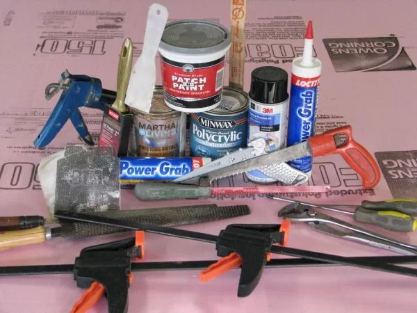
Here is an extensive list of the tools and materials needed for this project:
For the Styrofoam:
– Extruded Polystyrene
– Clamps
– Spray Adhesive
– Saws
– Mini Keyhole Saw
– Large Keyhole Saw
– Band Saw (optional)
– Bench Saw (really nice, but you can make due without)
– Hack Saw Blade
– Rough Wood File
– Fine Wood File
– Drywall Sandpaper (Black)
– Regular Sandpaper (Brown)
– Patch n Paint
– Minwax Polycrylic
– Dowel Rods
– Power Grab (comes in a tube, looks a lot like caulking)
– Hinge
– Plexiglass
– A Hard Wood(Oak)
– Assortment of screws
– Screwdriver
– Yardstick
For the Robotic Mechanism:
– 1/8″ Clear Tubing
– 1/4″ Air Compressor adapter
– Pressure regulator (300 p.s.i. max)
– 2 x 24V 3-way Solenoid Valves (50 p.s.i. max)
– 3 x Ball Valves (to act as flow regulators)
– Assortment of 1/8″ to 1/4″ adapters, fittings, tees, elbows, and nipples. (really personal preference)
– Wrenches
– Pliers
– Teflon Tape
– Vice (optional)
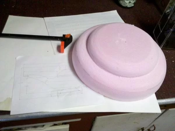
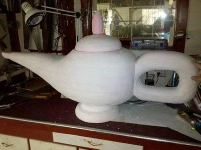
Step 3: Sculpting
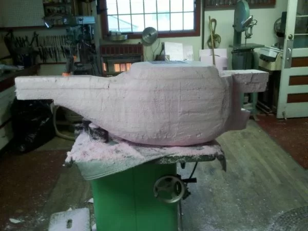
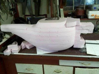
1. To start building your model, cut the styrofoam into sheets and layer them to make a block. If you know you don’t need some sections and want to save on material you can cut the general shape before you glue them all together.
2. Once you have your block setup the way you like it, use spray adhesive to hold the sheets of styrofoam together. If you know that you wont be sculpting where the glue will be USE POWER GRAB. Power grab is much stronger but it is very tough to sculpt it because when it dries it is hard as rock. I knew I was going to hollow out the inside of the lamp but wasn’t sure exactly where, so I used spray adhesive and it worked well. Spray both sheets of styrofoam and then lay them together. Repeat until you have a solid block (or whatever shape you want). I should warn you if you use too much spray adhesive you will eat the foam! Be careful not to leave drips or spray too much!
3. After all of your sheets are sprayed together, clamp them up and let them rest overnight for the glue to completely set.
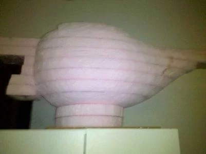
4. Now for the most time consuming part, sculpting. You can use a combination of the keyhole saws, hack saw blade, and files to sculpt your model. What I found worked best was to use the hack saw blade for long straight cuts, the keyhole saws for longer curved cuts, and the files to round things off. The files were crucial to the curves that you see on the nozzle of the lamp. Take your time! This is the most important step!
5. If your sheets of styrofoam are coming apart you can either: Put power grab between them and it will hold for sure OR put power grab on a dowel rod and put it through a section you know you wont be sculpting. Also, if you need to add satellite blocks to your main block to add details, just cut dowel rods and use them in conjunction with power grab to really hold on those parts for good.
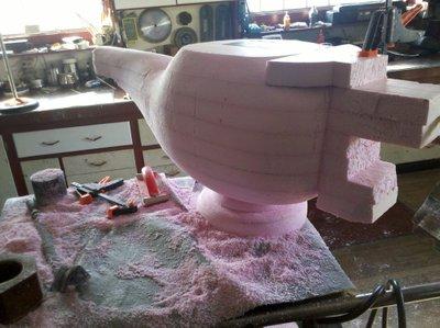
6. After your foam is sculpted, you can use the black drywall sandpaper and fine wood file to smooth out your model. The drywall sandpaper is important because it does not coagulate!
7. Give your model a final sanding with the finer sandpaper.
8. Fill holes and seams of your model with patch n paint. You can just smooth it on with your finger or a putty knife, which ever you prefer. But the trick is to leave it on overnight and then sand is so its flush with your model, don’d try to make this filler smooth with your styrofoam right then.
9. Sand your patch n paint spots and repeat until you’re happy with the overall shape.
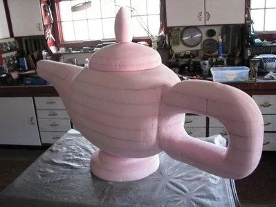
Step 4: Coating & Painting
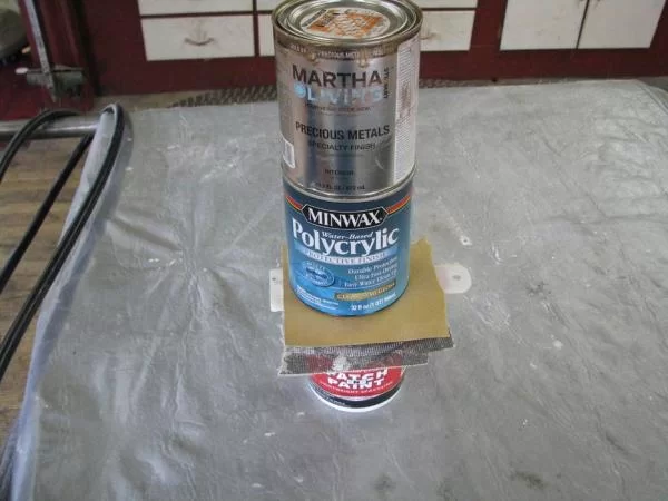
Next is the coating and painting. This is the scariest part of the process because you just worked so hard to sculpt your model you don’t want to mess it up! Well maybe this instructable will be a little reassurance for you. A great way to coat your model is with Minwax’s Polycrylic. It dries clear and gives a great glossy finish, paint sticks to it and so does patch n paint. So after your model is filled with patch n paint and you sand is perfectly smooth with sandpaper, stir up some polycrylic and apply it with a brush. You cant see the brushstrokes when it dries so don’t worry too much about that. However, you can see drips! So don’t be a sloppy painter! You can apply two or three coats of this with patch n paint in between or not, just whatever it takes to get a nice smooth finish. After the polycrylic is dry, you are ready to paint!
For my magic lamp I used a special paint called precious metal gold from Martha Stewart, I found it at Home Depot and it really made the lamp. It’s a PERFECT gold. More importantly, it is latex! Latex and Acrylic paints work well on the extruded polystyrene, but aerosol spray paint and oil based paints are a no-no. Even after we coat with polycrylic I am scared to ruin my work with a small hole in the clear coat, so I stayed away from spray paint and used latex. Theoretically, however, you could use spray paint on your model after you completely clear coat it to seal out the paint from the foam. One general rule of thumb is to look at the clean up instructions. If it says it needs to be cleaned up with mineral spirits you should not use it on your model. After a few coats of paint you are ready to install the pneumatic actuator! (or refill and repaint if you aren’t happy with the detail) 🙂
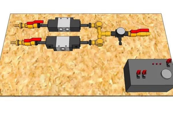
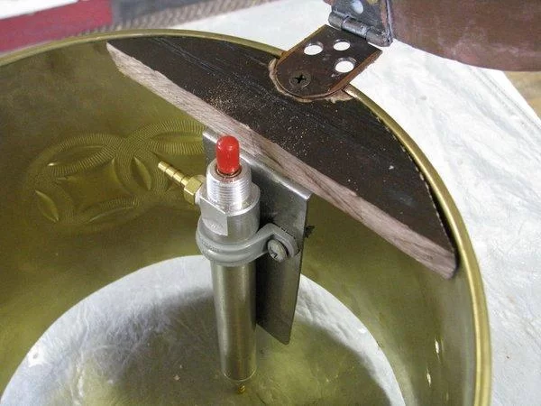
Step 5: Pneumatics Introduction
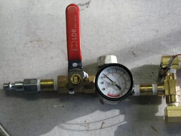
Here I am using a double acting cylinder. This means that to extend the piston a full “stroke”, I need to apply pressure to the bottom of the cylinder. To retract the piston, I need to apply pressure to the top of the cylinder. After a lot of calculations, I deduced that I needed to apply about 4 pounds of pressure to lift my lid at the angle that my cylinder was mounted. So, I regulated the pressure coming from my air hose to that amount. Now there is a difference between a PRESSURE REGULATOR and a FLOW REGULATOR! A flow regulator just inhibits the path of the air, slowing its speed. But when the air reaches its equilibrium, there is the same amount of pressure on both sides of the valve. A pressure regulator actually limits the amount of pressure on the output!
I used a pressure regulator to limit the pressure on my Pneumatic Control System to 4 p.s.i. and then used two 3-way valves to filter the air to the cylinder. A three way solenoid valve works by only connecting the air pressure to the cylinder when 24V is across its terminal wires, and then expelling the air in the cylinder through the third hole when the electricity is not flowing. The two ball valves you see after the solenoid valves are called flow valves, and they control the speed at which the air enters the cylinder and subsequently how fast it extends and retracts.
Step 6: Building the Pneumatics
For my magic lamp card box I used a pneumatic cylinder and solenoid valves from www.surpluscenter.com because I found they were less expensive than some industrial sites. I got my pressure regulator from Harbor Freight for six dollars and all of my brass fittings and ball valves from Menard’s. I would recommend laying out your setup at the store to prevent having to go back when you forget a piece. There are a lot of little fittings and adapters that are often overlooked. After you get your general setup ready you can go home and put it all together for good using some teflon tape, wrenches, and pliers. Your input should be coming from your air compressor and then it should immediately be followed by either an emergency shut off ball valve or pressure regulator. I would stray away from high pressure going through your rig as it can get dangerous. My maximum tank pressure is set to 40 p.s.i. and its being regulated down to 4 for my application. Your output from your Pneumatic Control System should be 1/8″ clear tubing that goes to your actuator. From there you just attach that and all that’s left is getting some electric to switch the 24V for your solenoid valves!
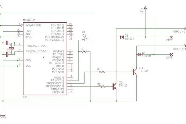
Step 7: Electronic Control Board
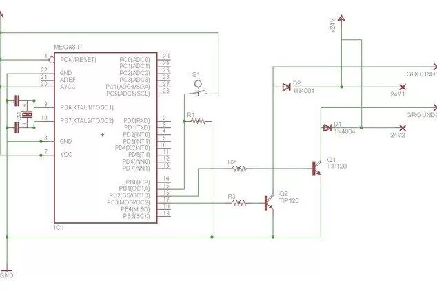
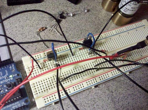
For the electronic controls, I used an arduino microcontroller to switch two TIP120 transistors on and off that alternate 24VDC to power the solenoids. The solenoids are used to push the actuator open and closed. This schematic is for the standalone arduino, but I attached my own personal board on top of the arduino board. The two diodes are used to protect the arduino output pins from the solenoids because all that the solenoids are are wire coils which act as inductors and try to maintain the magnetic field by producing a voltage in the opposite direction. The switch S1 shown above is a PIR motion sensor that I used to open the lamp when someone comes in front of the lamp. The code is pretty straight forward, when the switch is activated it opens the first solenoid valve for some determined amount of time and then opens the second valve to close the lid. I included a Serial.print so if you need to troubleshoot, simply open up the serial monitor and you can see if your problem is coming from your inputs or outputs. The code is posted below:
//Second attempt for magic mirror control circuit.
//Edited by: Drew Forchione on January 30, 2011.
const int SolenoidOne = 10;
const int SolenoidTwo = 11;
const int SensorPin = 12;
int SensorState = LOW;
void setup()
{
pinMode(SolenoidOne, OUTPUT);
pinMode(SolenoidTwo, OUTPUT);
pinMode(SensorPin, INPUT);
Serial.begin(9600);
digitalWrite(SolenoidOne, LOW);
}
void loop()
{
int SensorState = digitalRead(SensorPin);
if(SensorState == HIGH)
{
Serial.print(“Switch High”);
digitalWrite(SolenoidOne, HIGH);
delay(6000);
digitalWrite(SolenoidOne, LOW);
delay(10);
digitalWrite(SolenoidTwo, HIGH);
delay(6000);
digitalWrite(SolenoidTwo, LOW);
delay(10);
SensorState = LOW;
}
}
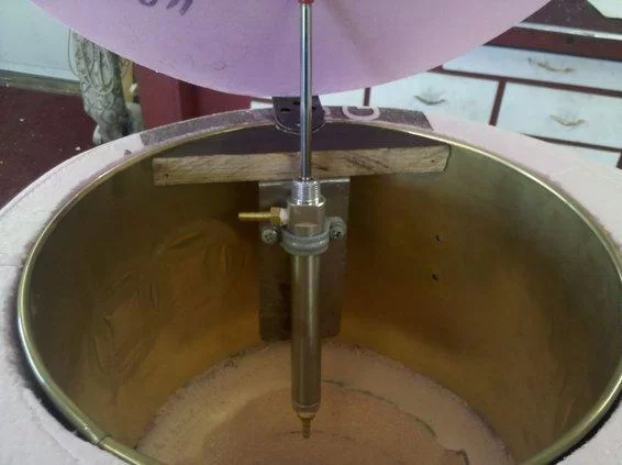
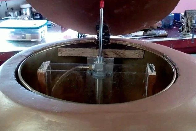
Step 8: Putting It All Together
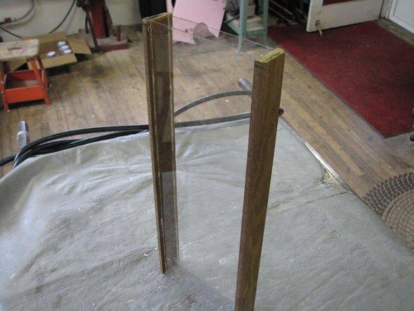
I made a chute from plexiglass and wood that allows the cards to slide down under the table into a collection bin. That is the first thing that goes inside the lamp. Then I slide in the round mounting for the pneumatic cylinder with the lid attached to it. The electronic controls, Pneumatic Control System sit under the table and only the two 1/8″ clear tubing is run up through the table to the lamp.
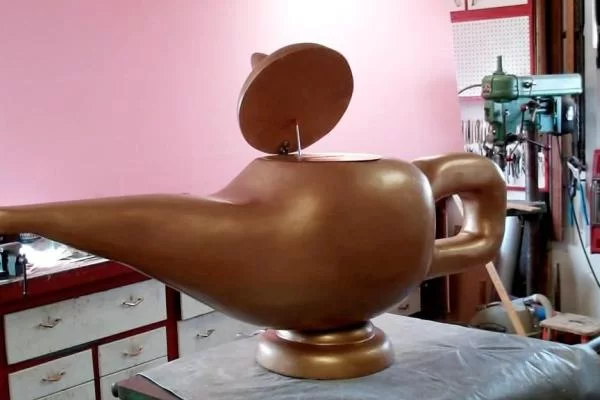
Step 9: Final Product
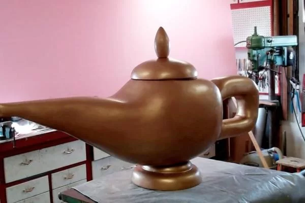
Finally! After the hours of sculpting, sanding, coating, painting, assembling, testing, and crying…the magic lamp card box is ready to go! This was a fun project and I’d like to thank my dad and grandpa for their knowledge and skills while they helped me.
[mom_video id=’-InSYETgHwo’]Source: Homemade Magic Lamp Card Box
About The Author
Hassan Zaka
I am an expert in accounting and possess diverse experience in technical writing. I have written for various industries on topics such as finance, business, and technology. My writing style is clear and simple, and I utilize infographics and diagrams to make my writing more engaging. I can be a valuable asset to any organization in need of technical writing services.
Follow Us:LinkedinTwitter