It has become apparent that WebIOPi is not yet compatible with the Raspberry Pi v2. If you are following this tutorial, you must be using the first-generation Pi. The link below for the B+ model is still valid, and this model will still work for this project. I’ve updated the Amazon links to point to the new Raspberry Pi B+ revision. Please note that if you’re going to use this version, you don’t necessarily need the USB wireless adapter listed below since the B+ revision of the Raspberry Pi includes a wired LAN port. Another note is that the B+ revision now uses Micro SD cards rather than the full-size SD card. The guide has also been updated to reflect this.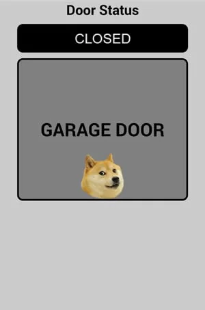
Recently, I read a blog post (http://freemansgarage.com/blog/?p=587) about configuring a Raspberry Pi to become an internet-connected garage door opener – meaning you can control your garage door from any device with an internet connection. I had never used, or really thought of using a Raspberry Pi for anything at all, or anything related to home automation, but this really piqued my interest. This project could prove useful for things like letting in a repairman or family member to your home when you’re not there, or if you simply lose your dedicated garage door remote or its batteries have died. Or it’s just really cool.
Along with the post I linked above, most tutorials I came across involved making circuits with breadboards or something similar for the magnetic switch sensor portion, but I didn’t have anything like that laying around and to be honest, it seems to over-complicate things. This project can be accomplished with no soldering or breadboards required.
To start with, the build list:
– Raspberry Pi (Updated this link to the B+ model since it is the most readily-available revision)
– Plastic Case for the Pi (This isn’t necessary, but will keep the Raspberry Pi safe. Has a hole to allow jumper wires through)
– 2-Channel Relay (One channel will be used for the door, the other could be for a future use)
– Wireless USB adapter (Raspbian has built-in drivers for this wireless chipset to make things easy)
– Magnetic Switch (This is only necessary if you want to be able to determine if the door is open or closed)
– Wire for the magnetic switch and connecting the Raspberry Pi to your garage door opener (I used extra CAT6 cable I had laying around, any 2-conductor cable ~20-24 gauge should be fine)
– Micro SD Card (You probably have some extras kickin’ around, 4GB or larger recommended, I went with 8GB in case I wanted to add stuff later)
– Female-to-female Jumper Wires
– USB to serial TTL adapter (This is also discussed below. It is optional, but this tutorial assumes you’re using a serial connection)
– MicroUSB Charger (You might have one laying around, at least 1 amp current recommended. Make sure you have a place to plug this in near your garage door opener)
– Wire Nuts (for connecting wires and resistors together, might be able to find them cheaper at a local hardware store)
– 1 10k Ohm resistor (You can get a pack of them from RadioShack for less than 2 bucks)
– 1 1k Ohm resistor (Again, a pack from RadioShack for a dollar and change)
First things first, you’ll need to get an operating system for your Raspberry Pi installed onto an SD card so there will be some type of user interface. Plug your SD card into your PC or USB SD card reader, then go to http://www.raspberrypi.org/downloads and download the image for RASPBPIAN Debian Wheezy (under the OPERATING SYSTEM IMAGES section). You’ll download a ZIP file that’s around 780MB. Once this is done downloading, open the zip file and inside you’ll find a file with a .img extension – extract this file to your PC and remember the location where you extract it. Since Windows doesn’t know how to handle this file natively, you need to download a program to write this image to the SD card. Download Win32 Disk Imager from http://sourceforge.net/projects/win32diskimager/ and install it. Run the program and you’ll get a box that looks like this: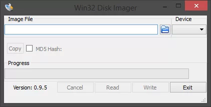
Click on the blue folder icon and browse to the folder where you extracted the .img file previously. Double-click on the .img file in the ‘Select a Disk Image’ dialog and you should end up with a window similar to this: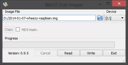
Make sure you have the correct drive letter of your SD card (or USB SD card reader) selected under the ‘Device’ heading. Once you’ve confirmed the correct device is selected, click ‘Write’ and let the program write the image file to your SD card. Once this process has completed go ahead and safely eject the SD card from Windows and insert the card into the bottom of the Raspberry Pi.
Now, depending on how you want to communicate with the Raspberry Pi, you’ll either need a USB hub to connect a mouse and keyboard to the Raspberry Pi and connect to a TV or monitor with HDMI, or connect to the Raspberry Pi via serial interface. I opted for the serial interface since I already had a USB to serial TTL adapter from another project. My instructions will assume you’re also using the serial method and already have the appropriate drivers installed for the adapter and have a COM port assigned. One thing to note, you should only have to connect the RX and TX cables to the Raspberry Pi since it will be powered via USB connection.
This is the Raspberry Pi PCB and diagram of where the GPIO, VCC, ground, and serial pins are located:
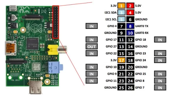
Now you’ll want to connect your USB to serial adapter pins to the UART0 RX and TX pins (8 and 10) and one of the ground connections on the Pi. The RX on the USB to serial adapter goes to TX on the Raspberry Pi and vice versa. You can also go ahead and plug in the wireless USB adapter at this point, but it won’t connect to your wireless network yet since the encryption settings are not configured. Once you have these wires connected you can go ahead and power up the Raspberry Pi. You should see a red power light below the blue 3.5mm connector as well as a green activity light that shows file system read/write activity.
If you don’t already have a terminal emulator program, you can download the free PuTTY program from here: http://www.chiark.greenend.org.uk/~sgtatham/putty/download.html. Run PuTTY and you’ll see a screen like this:
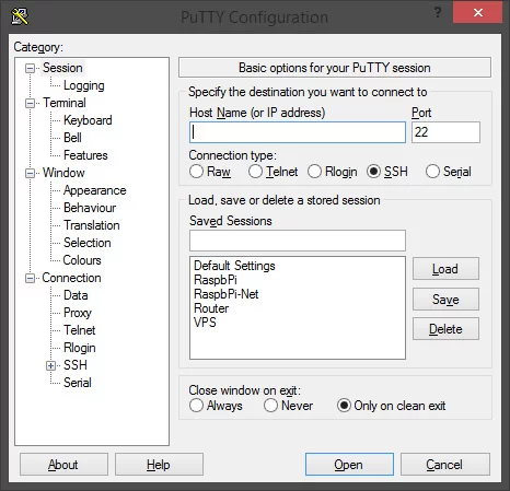
You’ll want to click on the ‘Serial’ radio button and make sure you input the correct COM port that is connected to your Raspberry Pi (COM3, for example). You’ll want to make sure and change the baud rate to 115200 (just type it in the box). Once you’ve done this click ‘Open’. A black window might be all you see, so press ENTER until a login prompt appears. The default username/password is pi/raspberry. You’ll probably get a message saying something about this being the first time you’ve run Raspbian and to run raspi-config to configure some settings – you’ll want to do this now. At your command prompt, enter:
sudo raspi-config
You’ll get a configuration menu – the only thing to bother with right now is enabling SSH connections so you can connect to the Pi via network later on. Go to Advanced Options, then SSH. It’ll ask if you want SSH enabled or disabled, select ENABLED and it’ll update the configuration and kick you back to the command prompt.
The first thing you’ll want to configure is the wireless connection, so you will need to assign an IP address to the Raspberry Pi. To do this some configuration file editing is necessary. The first file you want to edit is /etc/network/interfaces, so at the command prompt, enter the following:
sudo nano /etc/network/interfaces
This brings up the nano text editor with the contents of the /etc/network/interfaces file, like this: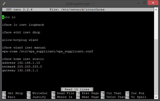
The contents of your file will be different, but you’ll want to edit it to resemble this picture. You can use your regular letters, delete, and arrow keys to make changes to the file. The part where your settings may differ from mine are the address, netmask, and gateway lines. My router is configured for the 192.168.1.xxx subnet, so I decided to assign the address as 192.168.1.10. Your router might be 192.168.0.1, so you could use an address like 192.168.0.10. The netmask will almost always be 255.255.255.0, but you’ll want to confirm the correct value in your router’s settings. The gateway address is the address of your router. Once you have the file edited to the correct settings, press CTRL+X to close the file. It will ask if you want to save the modified buffer, press Y. It will then ask the file name you want to write, just press ENTER. NOTE: If you get a permission denied error when you try to save the file, it’s because you did not have ‘sudo’ in front of your nano /etc/network/interfaces command. You’ll have to close the file without saving changes and at the command prompt, type:
sudo nano /etc/network/interfaces.
Now you need to get the Raspberry Pi connected to your encrypted wireless network. You should be back at the command prompt, so enter the following:
sudo nano /etc/wpa_supplicant/wpa_supplicant.conf
You’ll get a window that looks like this: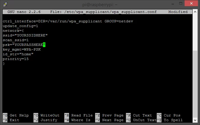
Again, use your keyboard to navigate the screen and match your file with what I have here. Replace YOURSSIDHERE with your wireless network name (2.4GHz only) and replace YOURPASSHERE with your WPA/WPA2 passphrase. Press CTRL+X to save, Y to confirm, and ENTER for the filename. Now it’s time to reboot the Raspberry Pi and see if it’s reachable via network. To reboot the Pi, at the command prompt type:
sudo reboot
Your Raspberry Pi will reboot and you’ll probably see the booting status in your terminal window. Eventually, you’ll arrive back at the login prompt – go ahead and login (again, the default user/pass is pi/raspberry).
Now you can check if your network settings took effect. To do this, at the command prompt enter:
ifconfig
You’ll see the loopback connection (lo) and your wireless connection (wlan0). In the wlan0 section you should see inet addr, bcast, and mask. As long as this has the information you entered in the /etc/network/interfaces file, you should be set! If you’re still having troubles with WiFi, try consulting this guide on ThePiHut. At the command prompt type:
sudo shutdown -h now
This will gracefully shut down the Raspberry Pi and halt all processes. The red power LED on the Raspberry Pi will still be lit, but the green activity light will stop flashing and you’ll see a shutdown message in the terminal window. Once the activity LED is done flashing, go ahead and unplug the power from the micro USB connector. Remove the serial cable jumpers, plug the micro USB cable back in, and restart PuTTY. This time, when you start PuTTY, leave the SSH radio button selected and type in the IP address that you gave the Pi previously (in my case it was 192.168.1.10). Now when you click ‘Open’ you might get a prompt about accepting the machine’s ID, go ahead and confirm and you should be greeted with the familiar login prompt. The login is the same as before (pi/raspberry).
Phew! It took me a little while to get the wireless working my first go-round, so hopefully my experience sped up the process for you a little.
The next thing to install is WebIOPi. WebIOPi provides a web interface to control the GPIO pins on the Raspberry Pi, and thus, the garage door opener.
You’ll want to make sure you are working in the home directory on the Pi, so at the command prompt enter:
cd /home/pi
This gets you back to your home directory where files can be written as necessary. Now you are going to enter several commands to get WebIOPi installed and configured to run at boot. Bear with me and just enter the commands as followed, one by one, waiting for the previous one to complete (you’ll get a command prompt after each step completes). Ready? Enter:
wget http://downloads.sourceforge.net/project/webiopi/WebIOPi-0.7.0.tar.gz
tar xvzf WebIOPi-0.7.0.tar.gz
cd WebIOPi-0.7.0
sudo ./setup.sh
sudo update-rc.d webiopi defaults
sudo reboot
Once the commands are all completed, you should end up back at the login prompt. At this point, WebIOPi should have installed successfully and already started running. To test this, open your web browser and navigate to http://192.168.1.10:8000 (you’ll want to make sure and use the IP address you assigned instead of mine). You should get an HTTP login prompt, and the default login/pass for WebIOPi is webiopi/raspberry. Is it working? If so, congratulations! If not, post a comment below and I can try to get you up and running.
If it worked for you, it’s time to get busy connecting some wires. Go back to your PuTTY window, login if necessary, and shut down the Raspberry Pi by entering:
sudo shutdown -h now
Once you get the shutdown message and the green activity light stops flashing go ahead and unplug the power from your Raspberry Pi.
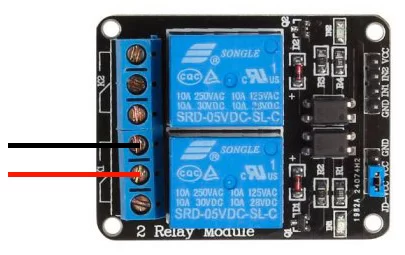
Alright, now get your bundle of jumper wires – you’ll need 3 of them, and also break out the 2-channel relay if you haven’t already. Here’s a crude diagram of how you want to connect the wires to your relay: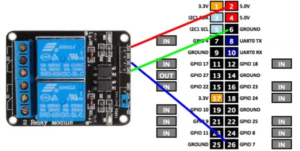
The connections are as follows: pin 2 (5v) on the Raspberry Pi to VCC on the relay, pin 6 (ground) to GND, and Pin 26 (GPIO 7) to IN1. Once you have this connected, the next step is to make sure you can control the relay with the WebIOPi interface.
Power the Raspberry Pi back on, open your web browser, and navigate to your Raspberry Pi’s IP address with port 8000 (again, mine was http://192.168.1.10:8000). Log in to WebIOPi (user: webiopi pass: raspberry) and click on GPIO Header – you should see a diagram of all the GPIO pins and their status. Find GPIO 7 on the bottom-right and click on the ‘IN’ next to it. Did you hear the relay click and a little LED on the relay illuminate? FREAKIN’ SWEET, RIGHT? Congratulations on making it this far, you’re NEARLY done. If you don’t want to have an open/closed sensor on your garage door, the only thing you really have left is to upload an HTML interace to your Pi and connect the relay to your garage door opener. I’ll go over that in a little bit, but first, I’ll tell you how to connect the sensor.
Getting the magnetic switch connected and working properly was the most time consuming part of this whole setup for me. Mostly because I’m terrible at reading circuit diagrams. My ignorance in reading diagrams resulted in the door status constantly flashing between open and closed, even though the door was indeed closed. The gist of this, from my understanding, is that the GPIO pin on the Raspberry Pi that gets used for an input for the switch floats between a high and low state and we need to prevent that from happening with resistors by ‘grounding’ the pin and making it stay in a reliable state.
I ran some CAT6 cable from the side of my garage door (inside the garage, of course) to the top of my garage door opener. You can kind of see the yellow cable in this picture (click for a larger image):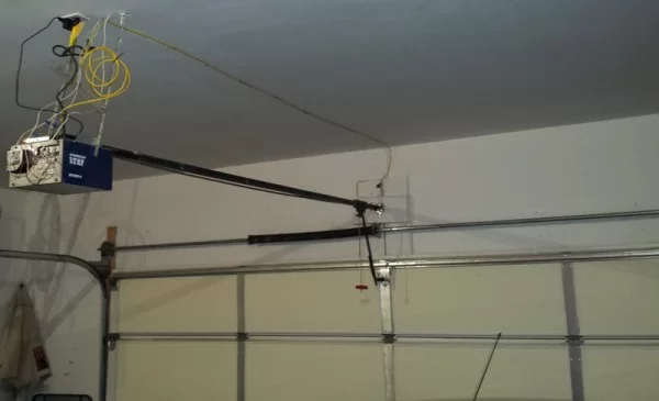
And this is what the sensor looks like on the left-hand side of the door (click for larger image):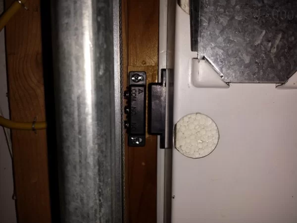
You can see that I have 2 wires connected – one to the COM (common) terminal and one to the NO (normally open) terminal. If you’re using the relay I linked at the beginning of the post, you’ll also want to connect your wires to these two terminals and ignore the NC (normally closed) terminal. I used the blue and white/blue wires from the CAT6 cable, but that doesn’t really matter as long as you use the same pair on both ends.
Below is an extremely crude diagram on how to connect the sensor to your GPIO pins with wire nuts. You’ll have to cut a few jumper wires in half and strip off some of the insulation so you have exposed wire to make your connections. The wire from the COM terminal splits off in two directions – one of the wires goes to the 3.3v pin while the other wire goes to GPIO 18. Make sure to include your resistors otherwise you’ll end up having a floating GPIO status. The N.O wire from the switch just goes to pin 14, which is a ground.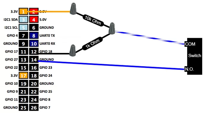
That wasn’t so bad was it? Now the last thing should be connecting the relay to your garage door opener. Most garage door openers should have at least a few screw terminals for buttons or lights, and when two of the terminals are connected electronically it should result in the door opening or closing. I found out which terminals I needed just by touching a wire between them – pretty simple. Here’s a picture of the back of my opener and you’ll see the red and black wires connected to the 2 leftmost terminals: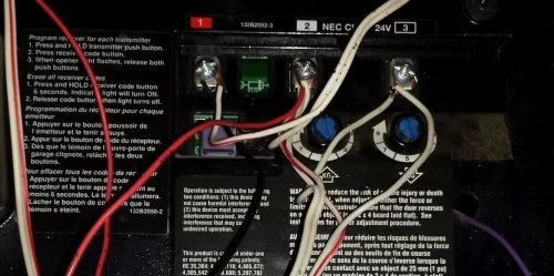 The red and black wires are going to my relay. The relay also has a normally open and normally closed state, so here’s another picture of where to connect the red and black wires:
I think at this point most if not all of the wiring is complete, the last thing we have left to do is upload an HTML file to provide a GUI for controlling our relay. I’ve made my documents available and here’s how you can get them on your Raspberry Pi:
Fire up PuTTY again, connect to your Raspberry Pi’s IP address, and login. You’ll want to make sure you’re in the home directory, so at the command prompt, type:
cd /home/pi
Then type the following to download the required files
wget https://www.driscocity.com/rpi/garage.html
wget https://www.driscocity.com/rpi/doge-static.png
wget https://www.driscocity.com/rpi/doge-action.png
wget https://www.driscocity.com/rpi/open.png
wget https://www.driscocity.com/rpi/closed.png
Now you need to move these files to the WebIOPi htdocs folder, so use the following commands and make sure to include the ‘sudo’ part or you’ll get a permissions error:
sudo mv garage.html /usr/share/webiopi/htdocs
sudo mv doge-static.png /usr/share/webiopi/htdocs
sudo mv doge-action.png /usr/share/webiopi/htdocs
sudo mv open.png /usr/share/webiopi/htdocs
sudo mv closed.png /usr/share/webiopi/htdocs
Got those all downloaded? Great, let’s check it out! Open a web browser and navigate to http://192.168.1.10:8000/garage.html (note that your IP address might be different depending on your settings). You should see an image like the one at the beginning of this post. Press the gray ‘GARAGE DOOR’ button, does your door open or close? BOOYA. You should see a little animation with the doge meme face and the door status should show whether the door is open or closed.
Here’s a video of what SHOULD happen:
Sorry for the focus problems, but you get the idea. This is what my whole assembly looks like:
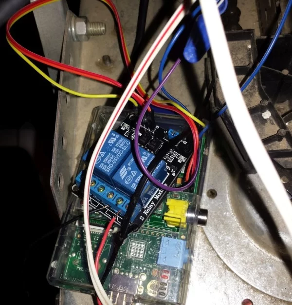
It’s a mess of wires currently, but it’s functional. Some day I’ll tidy it up.
If you want to be able to access your WebIOPi page from outside your local LAN, you’ll need to know your external IP address and do some port forwarding. I’ll explain this in another article.
At some point you’ll want to change your Raspberry Pi and WebIOPi passwords for security purposes. Here’s a link on how to change your WebIOPi login info: http://code.google.com/p/webiopi/wiki/PASSWORD and here is a link on how to change the Raspberry Pi login info: https://www.youtube.com/watch?v=zgoWIGXMHfM
Hopefully this write up helped you get your Raspberry Pi garage door opener up and running. I wrote this post over a period of a few days, so I’m sure there are some breaks or gaps in the instructions. If something seems confusing, please feel free to comment below and I’ll try to help you out.
If you found this howto helpful, I would certainly appreciate any donations via Bitcoin or Litecoin. Here are my addresses:
BTC: 1CTrxnhNnxtGgxFuBXwmYp3yHBPVr3HdaW
LTC: LNRPYj6RpVqPknBy9C1ppB6XFTnXbPTDug
About The Author
Hassan Zaka
I am an expert in accounting and possess diverse experience in technical writing. I have written for various industries on topics such as finance, business, and technology. My writing style is clear and simple, and I utilize infographics and diagrams to make my writing more engaging. I can be a valuable asset to any organization in need of technical writing services.
Follow Us:LinkedinTwitter