The keyfob deadbolt to my apartment never worked quite right because it is a copy of a copy of a copy. I am fairly certain that the keyfob deadbolt is original to the building and the property manager seems to have lost the original key years ago. As a result unlocking the door was always a pain. Changing the lock wasn’t an option, but eliminating the need to use a key was.

Parts:
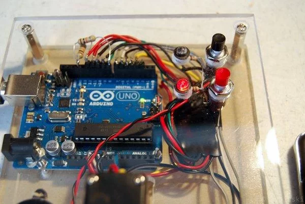
Arduino Uno
RF transmitter and receiver
Servo
2 Push Button Switches
Red LED
Green LED
Various Resistors
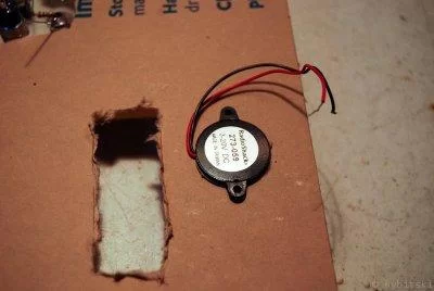
piezoelectric speaker
Perf Board
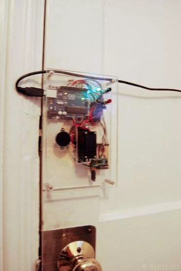
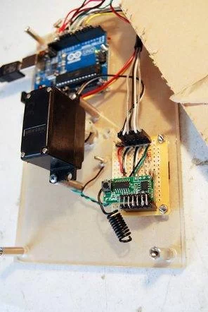
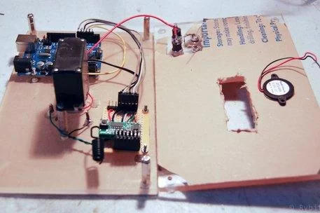
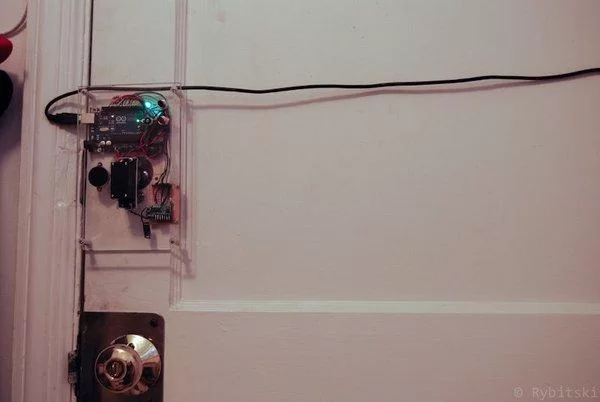
Step 1: Mounting Parts
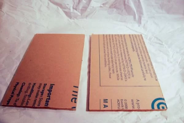
I used a couple of pieces of acrylic that I acquired in the dumpster of the plastic shop next to my place of work (they throw out alot of small pieces like this). Alternatively another material could be used if you don’t have access to acrylic, but it is easy to work with and looks cool.
Using a piece of paper trace the mounting holes for your dead bolt and transfer them onto your acrylic sheet. Since most dead bolts are going to be slightly different I am not sharing the template I made out of a piece of paper (mainly because it isn’t anything worth sharing).
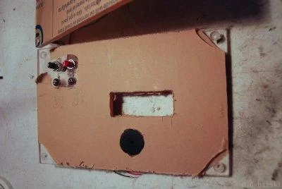
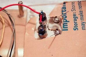
Leave the paper covering on while working with the acrylic. The paper makes it easy to mark where to cut/drill as well as protects the material from scratches. Once all of your cuts are made and your holes are drilled you can start installing components such as LEDs and switches.
Step 2: Servo
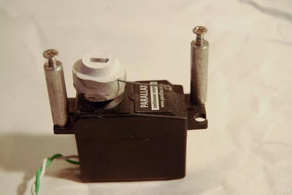
I used an old parallax servo I had in my parts bin. This small servo is more than strong enough to turn the deadbolt. In order to attach the servo to the lock shaft I used epoxy putty. Epoxy putty is very easy to use and is extremely versatile. The wire you see sticking out of the putty will be used as the arm for the limit switch.
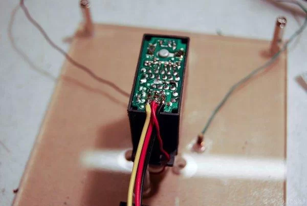
At some point the wires to my servo had been cut so I had to open the case and solder on new ones. I took that opportunity to solder on a second wire to the 5v line and connected it to the limit switch arm.
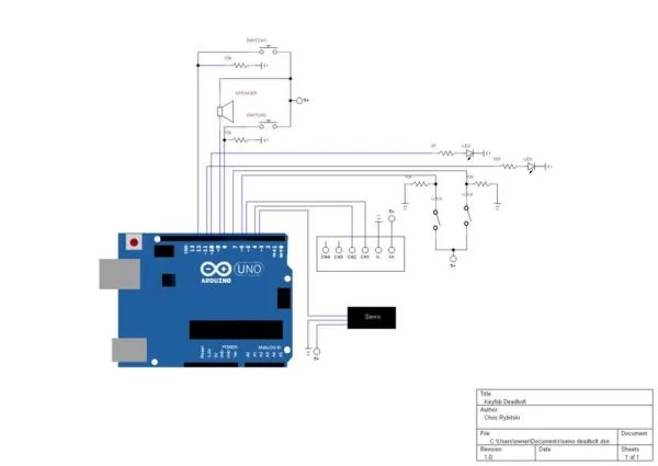
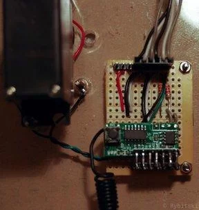
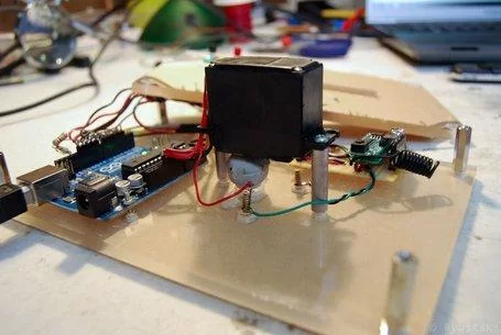
Step 3: Wiring
Step 4: Program
// turn CW to lock and CCW to unlock
//1700 CCW; 1500 Stop; 1300 CW
//written by Chris Rybitski
#include <Servo.h>
Servo deadbolt; // create servo
const int CWLimit = 6; // Limit Switch on 6 Unlock
const int CCWLimit = 7; // Limit Switch on 7 Lock
const int Redbtn = 12; //red push button
const int Blackbtn = 8; //black push button
const int GreenLED = 10; // Green LED
const int RedLED = 11; //Red LED
const int Ch1 = 5; //rf channel 1
const int Ch2 = 4; //rf channel 2
const int Buzz = 9; //buzzer
int Unlock = 0;
int Lock = 0;
int timer = 0;
boolean UnLcomplete = false;
boolean Lcomplete = false;
void setup()
{
Serial.begin(9600);
deadbolt.attach(3); // attaches the servo
pinMode(GreenLED, OUTPUT);
pinMode(RedLED, OUTPUT);
pinMode(Buzz,OUTPUT);
pinMode(CWLimit, INPUT);
pinMode(CCWLimit, INPUT);
pinMode(Redbtn, INPUT);
pinMode(Blackbtn, INPUT);
pinMode(Ch1, INPUT);
pinMode(Ch2, INPUT);
//set LED’s and Buzzer to be off by default
digitalWrite(GreenLED, HIGH);
digitalWrite(RedLED, HIGH);
digitalWrite(Buzz, HIGH);
}
void loop()
{
if (digitalRead(Ch1) == HIGH || digitalRead(Redbtn) == LOW){ //If remote or button is pressed
if(UnLcomplete == false){ //dont run unlock if door is already unlocked
Serial.println(“UnLock”);
Unlock = 1;}}
if (digitalRead(Ch2) == HIGH || digitalRead(Blackbtn) == LOW){ //If remote or button is pressed
if(Lcomplete == false){ //dont run lock if door is already locked
Serial.println(“Lock”);
Lock = 1;}}
//—————UNLOCK————————-
if (Unlock == 1){
timer = 0;
while (digitalRead(CWLimit) == LOW){
if (timer > 1500){
digitalWrite(Buzz, LOW);
delay(500);
digitalWrite(Buzz, HIGH);
}
else{
deadbolt.write(1700);
timer++;
delay(1);
}}
deadbolt.write(1500); //servo stop
digitalWrite(RedLED, LOW);
digitalWrite(GreenLED, HIGH);
UnLcomplete = true; //unlock complete
Lcomplete = false; //reset Lock boolean
digitalWrite(Buzz, LOW);
delay(100);
digitalWrite(Buzz, HIGH);
Unlock = 0; //reset
}
//————–LOCK—————————-
if (Lock == 1){
timer = 0;
while (digitalRead(CCWLimit) == LOW){
if (timer > 1500){
digitalWrite(Buzz, LOW);
delay(500);
digitalWrite(Buzz, HIGH);
}
else{
deadbolt.write(1300);
timer++;
delay(1);
}}
deadbolt.write(1500);
digitalWrite(GreenLED, LOW);
digitalWrite(RedLED, HIGH);
Lcomplete = true; //lock complete
UnLcomplete = false; //reset Lock boolean
digitalWrite(Buzz, LOW);
delay(100);
digitalWrite(Buzz, HIGH);
delay(50);
digitalWrite(Buzz, LOW);
delay(100);
digitalWrite(Buzz, HIGH);
Lock = 0; //reset
}
}
Step 5: Final Thoughts
About The Author
Hassan Zaka
I am an expert in accounting and possess diverse experience in technical writing. I have written for various industries on topics such as finance, business, and technology. My writing style is clear and simple, and I utilize infographics and diagrams to make my writing more engaging. I can be a valuable asset to any organization in need of technical writing services.
Follow Us:LinkedinTwitter