Step 1: Design
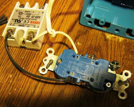
The controller is my own design Arduino using an LCD1602 for display and a Solid State Relay, SSR25DA to control AC for the crock pot.I also use a cheap USB power supply to provide 5Vdc for the Arduino. (see pictures)
Basic Theory: A temperature sensor is connected to the Arduino. The temperature sensor is placed in the crock pot submersed in water along with the food to be cooked. Two pushbuttons on the Arduino set the desired temperature. If the water temperature is below the set temperature, the SSR is turned on so AC is supplied to the crock pot and the water heats up. When the water temperature reaches the set temperature, the SSR turns off and the crock pot stops heating. Thus the water temperature stays at the set temperature.
Parts List
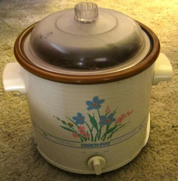
1 Crock Pot Simple design, on-off or high-low-off
1 Double AC box
1 Double AC cover
1 AC Outlet
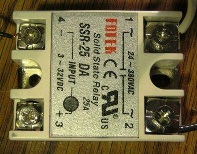
1 SSR25DA Solid State Relay (see picture)
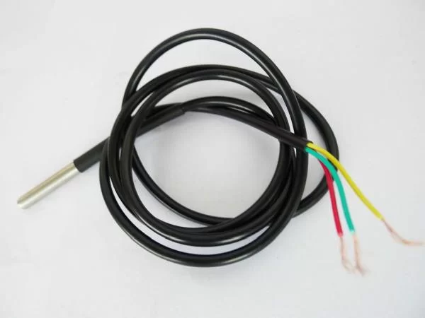
1 DS18B20 waterproof temperature probe
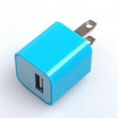
1 USB power supply (see picture)
1 L.O.G. souse vide PCB
1 ATmega328 microcontroller
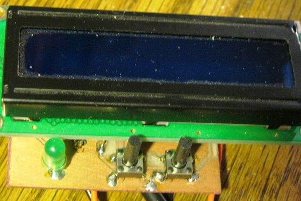
1 LCD1602 display
1 16MHz crystal oscillator
2 22pF capacitors
1 47uFd 25V capacitor
1 0.01uFd capacitor
1 LED, 5mm
2 10K resistor
1 4.7K resistor
1 1K resistor
(2 KF301 connectors) not used
2 pushbutton tactile switch (tall)
I purchased most everything off of ebay and at my local hardware store. The crock pot is borrowed.
Step 2: DS18B20 Temperature Probe
So you may ask, why did I select the DS18B20 for the temperature probe? There are many devices that are a lot cheaper.
The main reason is because they’re pre-calibrated. They are accurate to within ½ a degree C.
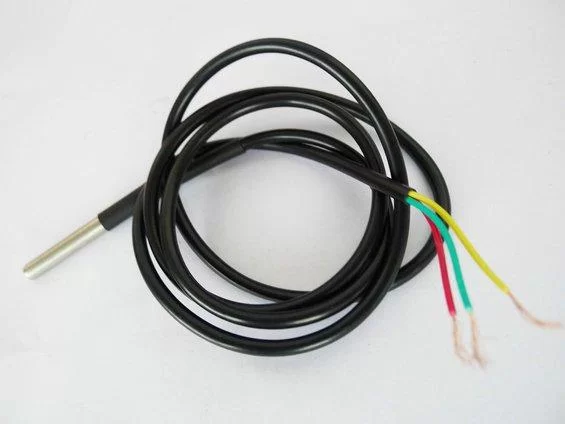
On ebay, the DS18B20 comes in two types: one is the TO-92 three lead package. The second is the waterproof type shown in the picture.
I have some of the TO-92 types and was thinking about making my own waterproof submersible one but I was feeling Lazy so I bought the waterproof version.
Here’s the datasheet
http://datasheets.maximintegrated.com/en/ds/DS18B20.pdf
The primary reason I selected the DS18B20 is the accuracy. It is calibrated to +/- 0.5C. Most of the other cheap temperature sensors have to (or should be) calibrated at various temperature points to achieve better accuracy.
Irrelevant Information: Calibration: A typical two point calibration is to use freezing temperature of water, 32F (0C)and boiling point of water, 212F (100C). But wait! This boiling point is only true at sea level. My altitude is about 4600 ft. so boiling water is about 203F. Okay, this is a lot of work and I’m LAZY so I will just assume that the DS18B20 is as accurate as claimed.
Secondary reason: the DS18B20 is digital as opposed to analog. Analog sensor accuracy varies with associated components and noise. Digital data is not subject to any of that.
Technobabble: The DS18B20 data is transferred serially, specifically SPI (Serial Peripheral Interface). But serial is digital. Simply speaking, there are two versions of digital data, serial and parallel.
Third reason: This one only a Geek can love. The DS18B20 uses something called a 1-wire buss. In theory what this means is that you only need one wire to connect the DS18B20 to the receiver (Arduino, in this case). In practice you need two wires as the circuit needs a ground. And full disclosure, I’m using three.
DS18B20 and the Arduino: So, of course the Arduino needs a special library for the DS18B20 or actually for the One wire. I think there may be variants on this library or at least different versions but I used this one:
http://www.pjrc.com/teensy/td_libs_OneWire.html
Here’s some more info on DS18B20:
https://arduinoinfo.mywikis.net/wiki/Brick-Temperature-DS18B20
I am also using the Dallas Temperature library. I think the only thing I’m using it for is the conversion of Centigrade to Fahrenheit, which I could’ve written myself. However, there’s a lot of other things you can do with this library.
http://milesburton.com/Main_Page?title=Dallas_Temperature_Control_Library
*******************************************************
WARNING: Some of these waterproof DS18B20 ebay listings show the color code of the wires. Mine did but the code was wrong. Since I had a TO92 version, I used an ohmmeter to compare. Red was 5V, Green was signal and Yellow was ground. You may have different results.
****************************************************************
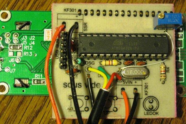
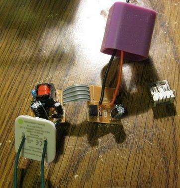
Step 3: L.O.G. Sous Vide PCB

There is a USB_BUB type connector like the one on a RBBB.
There’s places for connectors for 5Vdc, SSR and DS18B20 temperatrue probe.
This is a single sided PCB, so it’s easier for the DIYer to make. Because of this plus some space considerations, there are some unique problems. The Eagle Cadsoft schematic and PCB files are included.
The LCD1602 is attached to the back of this PCB.
1. The jumpers and all components except the pushbuttons and LED are soldered onto the component side.
2. The wires for the 5V-Gnd, SSR and DS18B20 come out the component side and are soldered to the solder side.
3. The pushbuttons and LED are inserted on the solder side. The LED is not inserted flush so that it sticks out and is easier to solder.
4. Male header pins are put in the solder side of the PCB and carefully soldered.
5. The LCD1602 is inserted onto the header pins and soldered.
(see pictures)
The schematic is attached. U$2 is for 5V in from USB power supply. The 10K potentiometer adjusts contrast on the LCD1602. The SSR connector goes to the SSR25DA (polarity is important) The DSx connections go to the DS18B20 temperature sensor.
I’ve included the Eagle Cadsoft files if you want to make your own PCB.
Step 4: DS18B20 Temperature Sensor
Each DS18B20 sensor has a unique address. You need to know that address so that you can talk to it.
I would recommend that you test each DS18B20 on a breadboard and get its address before hand.
If you haven’t done this or can’t remember, here’s a way to find it after it’s already installed on one of these PCBs.Connect the sous vide PCB to your PC with a USB adapter. I use a PL2303 module but you can also use a USB-BUB.
In the Arduino environment, make sure the correct serial port is selected. Under Board, select Arduino UNO.Under ‘File’ ‘Examples’ scroll down to OneWire and select
DS18x20_Temperature
In the sketch about eight lines down, you will see this
OneWire ds(10); // on pin 10 (a 4.7K resistor is necessary)
10 is the Digital pin used in the example. Change it to:
OneWire ds(2); // on pin 10 (a 4.7K resistor is necessary)
Upload the program to the Arduino.
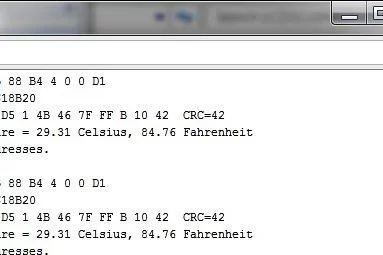
Open your Serial Monitor and set for 9600 baud. You should see something like the picture.
The first line shows the address: 28 6B 88 B4 4 0 0 D1
FYI, this is in hexadecimal. Write it down or put it in a database. This needs to go into the sous vide sketch. (The second line identifies the sensor and the fourth shows the temperature)
When you exit the environment, you don’t need to save the changes.
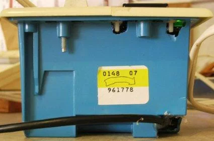
Step 5: USB Power Supply

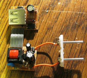
First test it to make sure it works. One of mine didn’t work. I have phones and tablets that are charged with USB.
The AC connector plate can be removed with a little prying. I used a utility knife.
The next picture shows what’s inside.
I removed the AC tangs, and the USB connector and replaced them with wires. (see picture)
Then put it back together. Put some hot glue on the ends. All this helps insulate the assembly. Alternative: you could use it as is. The AC outlet can be wired so one connector always has power and one is switched. The USB power supply is plugged into the first and a USB cable is plugged in and powers the ‘Arduino.’
Step 6: Arduino Sketch

You need the OneWire and DallasTemperature libraries.
I also replaced the LiquidCrystal library with LiquidCrystal_I2C library by Francisco Malpartida. (Attached)
Sketch is attached.
You must change the following line to the address you recorded.
DeviceAddress thermometer = { 0x28, 0x88, 0x58, 0xBD, 0x04, 0x00, 0x00, 0x6C };
(The 0x s before each number means it’s a hexadecimal number)
I set the minimum temperature to 43C and the maximum to 84C. You can change these.
The sketch can be loaded with just the USB_BUB adapter for power.
The LCD contrast can be adjusted with the potentiometer. (You will probably have to readjust it when you have it connected up to the internal power supply)
The display shows the Set temperature in Fahrenheit and Centigrade on the first line.
The second line shows the DS18B20 temperature.
The set temperature can be adjusted with the up and down buttons.
If the probe temperature is less than the set temp, the LED will be off and the SSR on(heating the crock pot).
When the probe gets up to within 2C of the set, the LED will slowly blink. When it gets to the set temperature it will be on steady.
Technobabble: I added a little hysteresis so the temperature shouldn’t overshoot the set temp by very much.
Step 7: Assembling Sous Vide Box
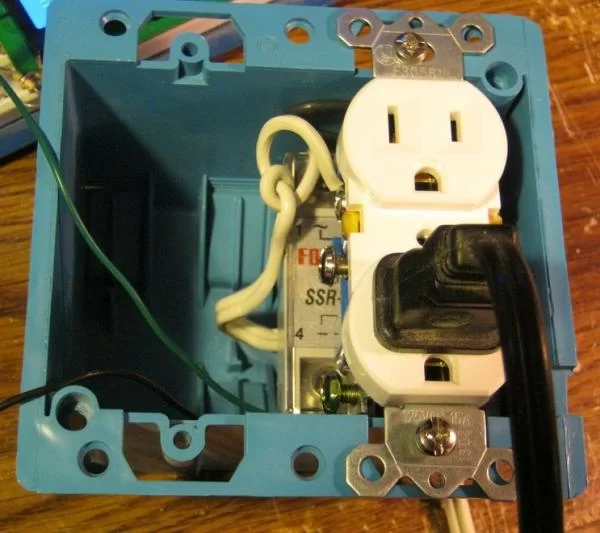
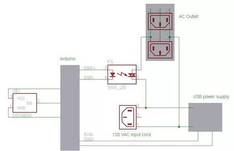
The wiring diagram shows how everything is wired together. For US users, the AC pin that’s shorter is the ‘hot’ side and is the one that should be switched.I used an old AC plug for the power connector.The double outlet cover had to be modified to fit the LCD1602 and mounting holes.
I used a dremel clone and did a lousy job. Yes, it cracked the plate, so I superglued it back together. I also drilled the holes for the mounting screws, the LED and the up and down buttons.I attached the LCD with nylon screws, attached the AC outlet to the box and tried fitting in the cover. Well, the PCB extended into the box so I had to cut a notch out for the PCB. I hadn’t planned any of this out but this was helpful as the PCB is just suspended by the LCD pins and the notch helps support the PCB. I also had to drill and dremel clearance notches for the LCD mounting screws. (see pictures)Assembly: The SSR25DA goes on the bottom of one side with the AC outlet above it. My SSR25DA came with a cover to help insulate it.
The USB power supply goes in the bottom of the other side with the PCB assembly above it. The DS18B20 also exits the bottom of the box.
Wire up per diagram.NOTE: I used too heavy a gauge wire. This made it very cumbersome to get it all crammed in there. Something like 22 gauge wire would be fine for the 5V and the SSR.
Step 8: Operation
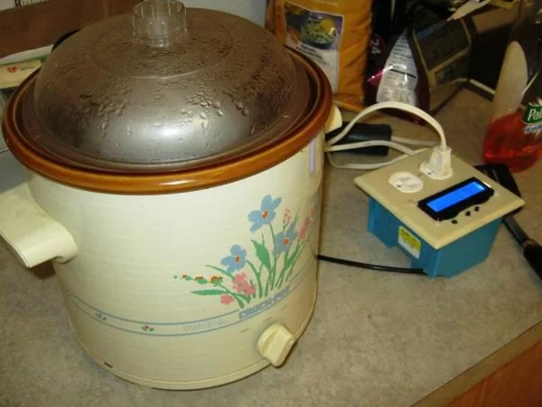

I made a little wire rack to suspend the DS18B20 probe in the water so it wouldn’t be touching the crock pot or the food packet. I used AC copper wiring and soldered connections.Suggestion: Warm the water up to set temperature before adding food.Plug the crock pot into the sous vide outlet box.
Put the DS18B20 into the wire rack. I used a tie wrap to hold it in place.
Put the rack into the crock pot.
Add lots of water.
Plug the outlet box into AC.
Set the temperature.
Turn the crock pot to High or On.
Wait for the water to reach set temp.
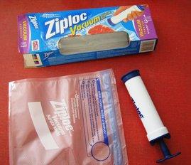
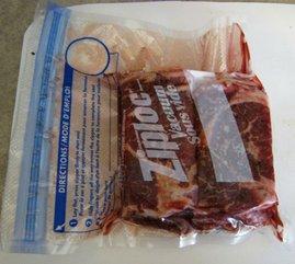
(I have a couple of IR thermometers and verified that the set temperature was what it was supposed to be)I bought a ZipLoc vacuum starter kit.
Put the food in the bag.
While expelling most of the air, close the top seal very tightly.
Put the vacuum pump over the round spot.
Pump out the air.When the sous vide reaches set temp, place the food in the crock pot. I placed a dish over it to help hold it under water.
This pieces of roast took about 15 minutes to get back to set temperature.
Once set temperature is reached, you can set the crock pot to low. I don’t think it’ll make much difference.
Cook the food for an adequate amount of time.Since I forgot about it, It cooked for 30 hours. The meat was supertender. I ate it with a fork. One of the nice things about sous vide is that ‘cooking’ time is not really critical. It’s great for an OLD Geek.
About The Author
Hassan Zaka
I am an expert in accounting and possess diverse experience in technical writing. I have written for various industries on topics such as finance, business, and technology. My writing style is clear and simple, and I utilize infographics and diagrams to make my writing more engaging. I can be a valuable asset to any organization in need of technical writing services.
Follow Us:LinkedinTwitter