Last year my Wife and I started a new tradition of building a LED Gingerbread house for Christmas.
We had a few nicely decorated houses last year, and I wanted to do a little more this year.
Adding LEDs makes everything better, so that is exactly what I did!
This instructable will show you how to wire up a ginger bread house with many LEDs (41 in this case) while only using a few pins of a micro controller to control them all.
By using charlieplexing, we can have individually addressable LEDs without the need for shift registers or a micro with a lot of IO pins.

Step 1: LED Wiring


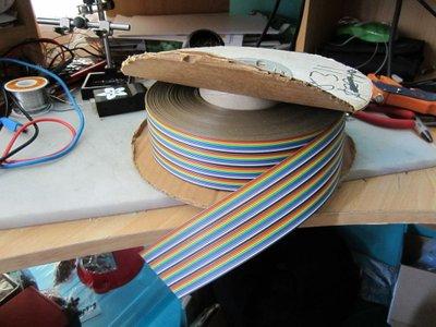

If you can take the advice from the next step, lucky you, you can skip the tedium!Still with me?You will need a fair amount of wire here, and it is very helpful if you can get pairs of wires that are connected.
I was given a big roll of ribbon cable, which made this task a lot easier.
After cutting a length of cable, I simply split it into groups of two wire.
So with wire and LEDs handy, lets get started.
Clip the leads of the LEDs so they are short, but still long enough to solder to.
Hold onto the clipped legs, they can be useful later on.
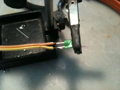
Put the clipped LED in a pair of helping hands to hold it still.
Strip the wires and put it in the other clip of the helping hand.
It helps to tin both the wire and LED legs before soldering them together.
Line up the wire with the LED and solder the wires to the legs.
It might be a good idea here to stick to a colour scheme if you can (red for anode, black for cathode), but I had a lot of different colours, so I didn’t bother.
It is easy to determine which is which later, but you might make your life easier if you can do it.
For the other end of the wire, I originally left it bare (but tinned).
After using it like that, I realised I needed a better option.
As I connected all of the wires through a breadboard, I found it easiest to solder breakaway headers to the other end of the wire.
Just like the LEDs, tin both, use helping hands and solder them together.
Step 2: Threading LEDs

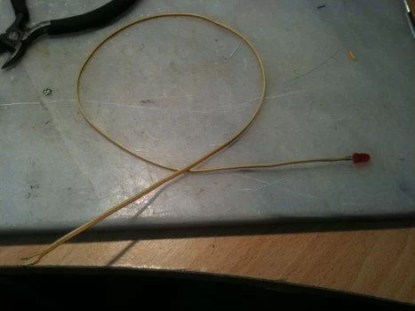
This can be achieved by soldering the LEDs onto long wires, and then threading them through the house.We started the house late this year, so I had to make the LEDs on wire myself, but if you have time to spare, you can buy them pre made:
http://www.aliexpress.com/product-fm/504804787-20-x-Red-LED-Lamp-Light-Set-25cm-Pre-Wired-5mm-12V-DC-wholesalers.htmlIf you are making them yourself I would suggest you use some heat-shrink tubing over the LED leads, I simply ran out of time to buy some.
Either way, you need to thread the LEDs wire first through the gingerbread.
We found it helpful to make a guide hole using a toothpick.
Step 3: LEDs in the Roof and Tree


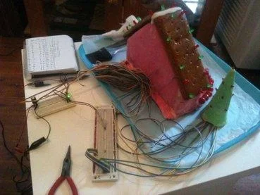
Now that you have soldered all of your LEDs up, you need to install them in the house.
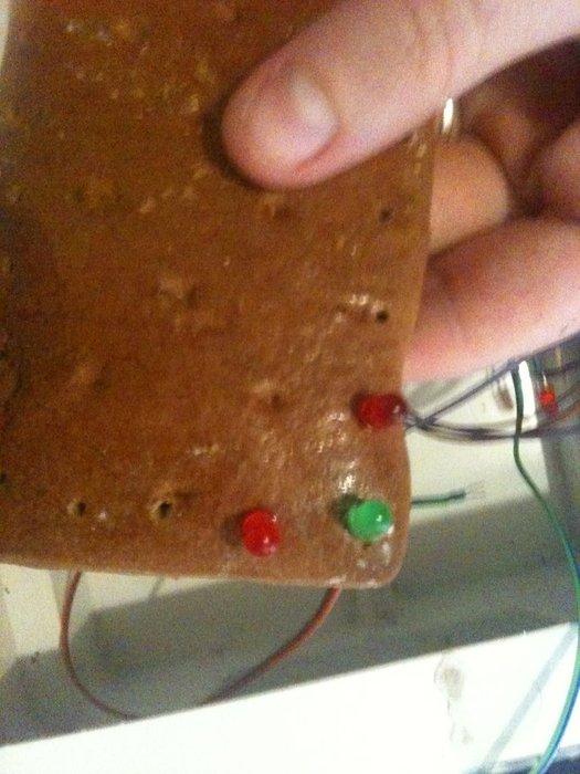
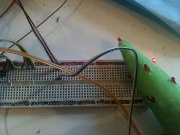
I put all of the 5mm LEDs in the roof, and then some 3mm LEDs in the tree.
For the house I had to cut a small exit hole in the back.
The tree is just an ice cream cone covered in fondant.
With wires of different colours all bundled together, I needed to work out the polarity of the wires and which wire mapped to which LED.
To do this I set up a small power supply (plug pack & 5v regulator), and tested wired pairs to determine which LED and in which direction to connect the wires.
I did discover here that some LEDs didn’t work, likely due to poor solder joints.
At this point though it would have been too hard to fix them, so I simply accepted some “dead pixels”!
Step 4: Charlieplexing the LEDs

To power them all I used a technique called “Charlieplexing”.
This is a neat trick which uses the fact that LEDs are diodes (current only flows one way) and that micro controllers can have 3 states on their pins (High, Low and High-impedance / disconnected).Putting it all together, charlieplexing allows us to access n*(n-1) less (where “n” is the number of micro controller pins you are using).I needed 41, and the closest combination was 42 from 7 pins: 7*(7-1) = 42
If you want to understand the concept in depth, this instructable is where you should start:
https://www.instructables.com/id/Charlieplexing-LEDs–The-theory/
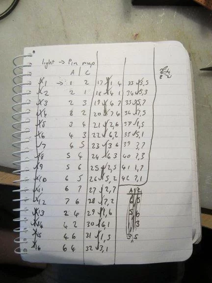
I drew up a schematic in Fritzing for how all of the LED connection combinations.
I then wrote down all the wiring combinations so I could track what I was doing.
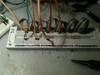
To connect all of the LEDs into this charlieplexed matrix, I decided to use a breadboard.
This kept everything flexible and reusable for future projects.
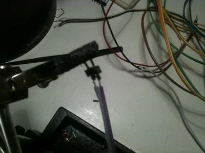
As I said earlier, I did not use a consistent colour scheme to mark the anode and cathode of the LEDs, so as a result I had to test them before use.
To achieve this I put together a small breadboard with 5v regulator, a current limiting resistor and an LED to show it was powered.
From here I just had to plug the LED (wires) being tested into the breadboard to figure out which LED it was, and which wire was the anode / cathode.
I’ll cover how they were all connected in a breadboard in the next step
Step 5: The Messy Breadboard
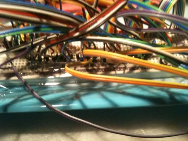

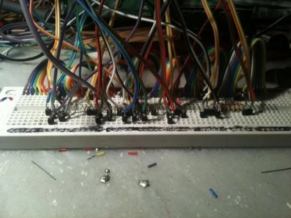
It took a few tries to get a layout that worked, but this is what I came up with.I started by splitting some ribbon cable into sets of 7 wires.
I tinned all of the ends and plugged it into the board to extend the number of slots I had for each pin.
I also used wire to bridge the two sides of the breadboard, to give me even more space.Originally I had resistors in place for current limiting, but due to the way charlieplexing scans, I was able to get away without them and I got slightly brighter LEDs (a smaller display will likely need them still).
Using the schematic from the previous step, I wrote down all of the combinations and crossed them off as I made the connection.
I changed my mind a few times in how I was connecting things up, which is why I seem to have 3 different marks for “done”!
With everything plugged in, I connected the Arduino to the board, and started work on the code.
Step 6: The Code

Before you look at the code, I have to say that I had grand plans, but ran out of time.
As such I have a lot of dead code which I had planned to have do many different animations, but as the Christmas party approached I shortcut it all and simply turned LEDs on in sequence.
This worked out very effectively as I had connected the LEDs in no particular order, so it appeared random, and it helped hide the LEDs that had failed.
So, the code…
I put it up on GitHub:
https://github.com/NathanWilliams/GingerbreadHouse2011
You can browse it, fork it or simply download a zip from there.
To understand the code, the best place to start is hal.cpp (Hardware Abstraction Layer).
To make a charlieplexed matrix look as if all LEDs are on at once, we need to cycle through them quickly enough to fool the eye.
To do this I used an AVR timer to trigger an interrupt when a set amount of time has passed.
When the timer interrupt fires, the next LED is displayed.
If it is on or off depends on the “display” which is an array of 42 booleans, true if an LED is to be on, false for off.
Display LED sets the right combination of output pins, and sets everything else to “disconnected” (high impedance).
Everything else happens in the main file (yes, everything else is dead code…).
Even most of the code in this file is dead code, but I left it as a starting point for next year.
All that really matters is setup and FrameCallback.
FrameCallback is a function which is passed as a callback function which is called from the refresh interrupt based on the number of frames that have been drawn.
As I am drawing at 60 FPS, I set the callback for every 15 frames, or ~250ms.
Step 7: Video!

About The Author
Hassan Zaka
I am an expert in accounting and possess diverse experience in technical writing. I have written for various industries on topics such as finance, business, and technology. My writing style is clear and simple, and I utilize infographics and diagrams to make my writing more engaging. I can be a valuable asset to any organization in need of technical writing services.
Follow Us:LinkedinTwitter