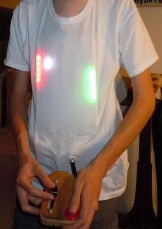
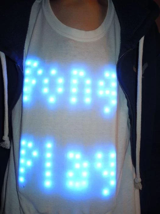
This is my Halloween costume for the year 2013. It’s been in the works for about a year and has taken quite a few man-hours to create. The screen is 14 by 15 pixels, so, pretty low resolution but it can still do some fun things. It is a physically flexible screen in all directions, although it cannot be folded without damage. It has a controller consisting of a single button and slide pot, connected to a pro mega via USB. To keep it alive for a long time it employs two monstrous 2200 mAh batteries wired in series to get the necessary voltage, and then a 5 Volt regulator to make it usable. All the electronics are place in pockets on the inside of the shirt so they can be removed and so the shirt can be washed.

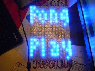
It plays a functional game of pong. It first graces one with the words “PONG PLAY” in lovely blue lettering using a modified version of the Tom Thumb font (can be found at http://robey.lag.net/2010/01/23/tiny-monospace-font.html). After five seconds the option can be given to press the button to move on, or to not press the button and leave a perfectly good experience behind. When one chooses to press the button, the game begins. A red paddle on the right is the computer paddle and the green paddle on the right is the player paddle, which is controlled by the slide pot to move up and down. The ball bounces around as each side tries to score a point. The player can hit the ball with the edge of their paddle to speed it up (a nice feature) while the computer cannot do this, and instead ends up being stuck with moving slightly slower than the ball. When a point is scored a pixel changes to white on the scoring sides paddle. It counts in binary from the bottom. where green or red is zero and white is 1. 21 is the score to win (or lose depending on who get’s 21 points) and so when the player paddle reads 10101, the “YOU WIN” text is displayed. Once again in modified Tom Thumb. The same happens but with “YOU LOSE” displayed instead. After a win or loss the game restarts to the point right after Pong Play. To restart entirely the restart button on the “Magic Box”, also known as the-box-with-all-the-electronics-except-the-screen, is pressed.
Step 1: Materials and Tools
Things marked with a * are optional but recommend
And so in no particular order…
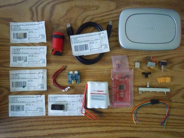
Materials:
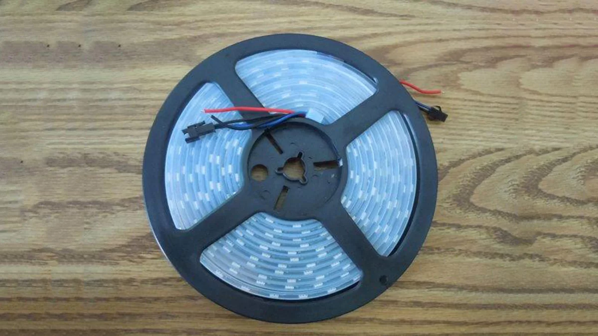
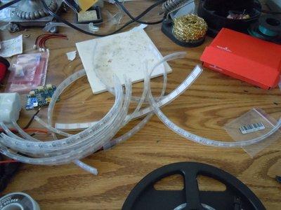
4 Yards of Adafruit Neopixle 60 pixle per meter strip
1 T-shirt
*1 pair of Suspenders
1/2 yard of fabric will be more than enough (Non stretchy weave is preferred)
6 foot USB A male to USB B male cable
1 USB A female connector
3 2 pin JST female connectors
4 2 pin JST male wires
battery charger
2 6600 mAh batteries
1 Arcade style Button
1 arduino pro-mega
1 FTDI header
1 USB B female connector with breakout board
1 on/off switch (toggle)
1 reset switch (toggle or momentary)
1 slide potentiometer
*1 slide pot knob
1 high amp connector pair
*1 project case
1 5V 3+ amp voltage regulator
a small bit of plastic
some solder
some wire
some thread
*some hot glue
*some elastic
some time (Maybe a little bit more than “some”)
some perseverance (You will probably need quite a bit of this actualy)
some heat shrink tubing or electrical tape
some super glue
some iron on backing
Tools
*Helping Hands
Normal Hands (or someone with access to them)
Soldering Iron
*Hot Glue Gun
Dremel or Sandpaper
Chisel
Wire Strippers
Wire Cutters
Staple Gun
Screw Driver
Saw
Pins
Sewing Machine
Fabric Scisors
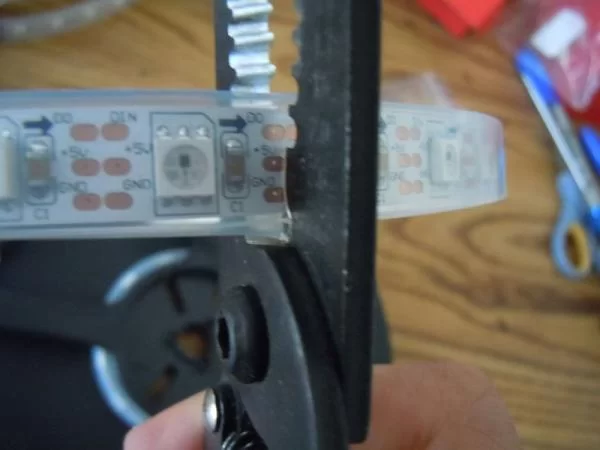
Step 2: Cut the LED Strip Into Smaller Strips
Step 3: Soldering the Screen Together
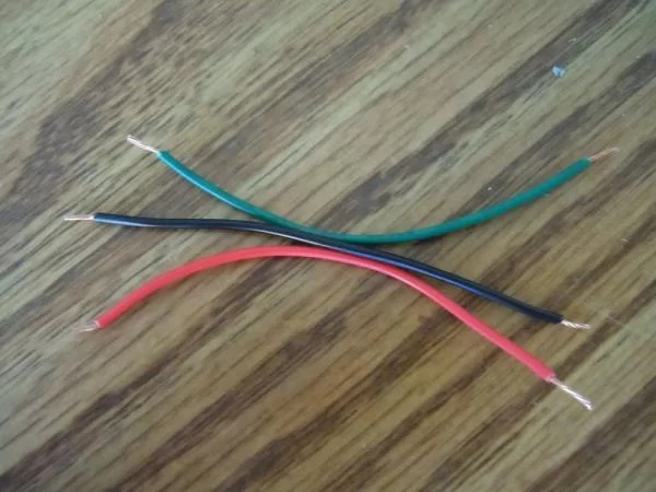
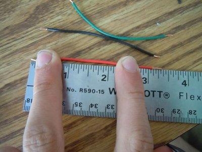
Take the wire and cut it into about 3.5 inch (9 cm) segments. In my case I have three different colors to make it easier to keep straight when soldering, but one color would work just fine. You will need about 40 of these little guys, but cut a couple more just in case.
Once You have finished cutting the wire, strip and tin the ends (If you have soldering experience you can skip to the next paragraph), meaning after you remove the little bit of plastic put some solder on the ends of each wire. Don’t heat the solder and try to move to to the wire, heat with you’re soldering iron from the bottom of the copper and put the solder on the top. Be patient and wait for the hot wire to melt the solder. It is tempting to tough the soldering iron to the solder to get it started (My impatience and I know exactly how you feel) but the solder won’t stick as well. Do the same for the exposed copper traces on each end of the strip sections. If it already has solder don’t worry about it. For the strip you may want to build up a little mound to make it easier later. When working with the strip, do it quickly, and try to not spend to much time applying heat to the strip. Only do what you need to do to melt the solder onto the trace.
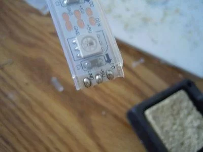
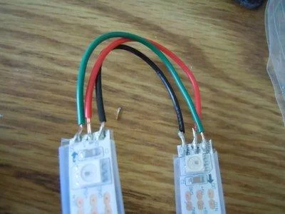
Solder a wire on each trace to the end of the first strip (The first strip being the one with the wires and connector, solder it to the exposed end). If you look at the strip you will see little arrows on it going up to the end where you soldered the wire. Take another strip so that the arrows are pointing the opposite direction, and solder the wire coming from the GND trace to the GND trace of the other, the +5V to the +5V and so on. Repeat this making sure the arrows switch directions after every section so that if you were to follow them it would zig zag up and down, and that it could be stretched out to on long strip in the end.
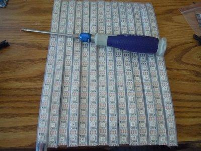
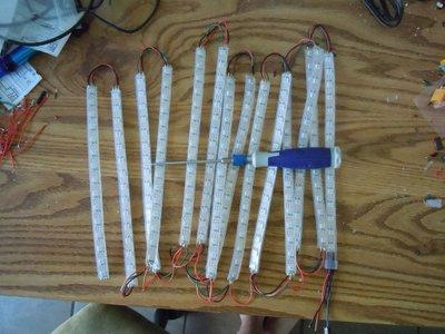
Once all 14 strips have been soldered, lay them out and line then up so the LED’s form a grid. Then keep them together using a method that can be removed later without damage to the strip. I used scotch tape. It’s sticky enough to keep everything together but not so sticky as to leave a residue. I do not recommend anything to permanent, like staples or duct tape.
Once everything has been taped together solder a wire from the strip on the bottom +5V to the one immediately next to it. Repeat until the the entire bottom has the power taps going all the way across. This is so the screen doesn’t dim as the line of LEDs progress.
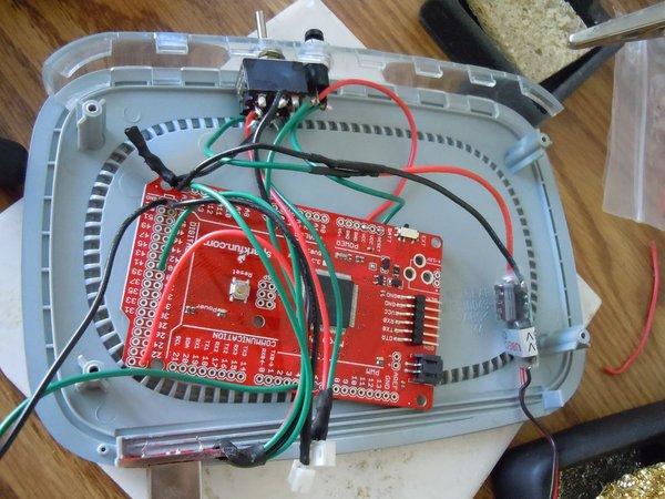
Step 4: Soldering the Core Electronics
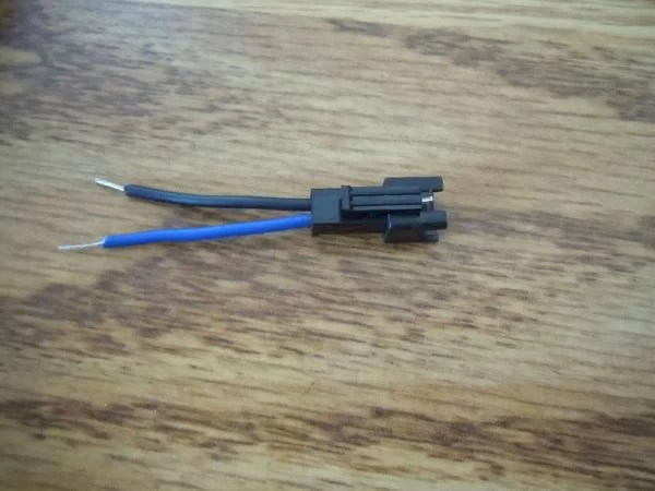
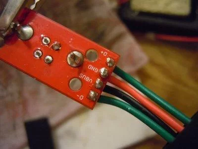
Solder the USB B breakout board (BOB) to the USB B connector. Solder the appropriate wires to the USB A connector. I advise looking at the pin-out of the connector as found at this website, http://image.pinout.net/pinout_USB_files/pc_usb_connectors_pinout.png. Don’t worry about where to solder the other ends of the wires on the USB A connector right now; that will be covered in the controller step. Cut the data connector from the strip, the female connector, not the male connector (The female connector is gotten from the other end).
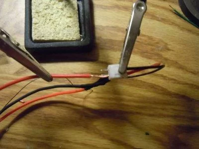
Solder the male JST connectors to the ends of the battery so that red goes to red and black goes to black. Melt heat shrink tubing over the exposed wires (slid over before soldering) so that they don’t short or use something else like electrical tape or hot glue. Solder some wires to the all of the female JST connectors. Be sure to have a male end plugged in so that the pins don’t shift around. Be careful of polarity and make sure the wires match with the male connectors. Solder wires to one the high voltage connector (but not it’s pair), once again, making sure any colors match up and that they are plugged together to prevent any shifting pins.
Solder the female just connector/wire assembly so that they are wired in series, not parallel, to get it past the threshold voltage for the power regulator. So, solder the positive wire to the negative wire of the other assembly so now we have one un-soldered positive wire and one negative un-soldered wire and the two soldered wires are soldered to different connectors. Take the negative wire and save it to be soldered to the negative wire elsewhere. Now take the positive wire and solder it to the switch If there are three or more pins (or more than one way of being “on”) solder it to the middle pin. Note the “Middle pin” may not physically be in the middle. The way to identify it is to find the pin that, when the switch is on in any state will always be connected to another pin. If no pin is like this then you have a very special switch; just connect it to any pin and make sure the next wire soldered to the switch will be connected to that wire in at least one on state.
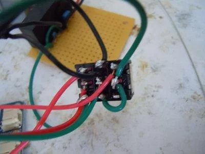
Now solder the positive intake wire on the voltage regulator to the opposite end of the switch, as discussed above. Solder the postive voltage out to the positive end of the un-soldered high current connector. Take the negative intake wire and solder it to the negative end of the high current connector. We’re now going to solder the power in parallel to the Arduino and Power strip. Now take the voltage regulator output wires and solder two pieces of wire on both the positive and negative ends so they come out in a Y shape. Solder a two pin connector to the positive and negative wires of the led strip assembly. It doesn’t matter what type of connector you use, it can be JST or in my case some power/audio cable or something (I’m not sure, and I apologize for not having any pictures). Solder one of the positive power wires to the positive end of the opposite connector for the light strip and one of the negative wires to the other pin on the connector. Do the same but for a male JST connector/wire assembly. All the while remember to insulate the solder joints to avoid shorts.
Now onto what to do with the USB B connector. Solder the positive wire to a 5v hole on the Arduino Pro Mega. Take the ground wire and solder it to a GND hole. Take the D+ and solder it to the digital pin (or in this case, hole) 40. Solder D- to analog pin 15. Solder the data end of the female connector which mates with the LED strip male connector to data pin 6 and the ground wire to a GND pin. Masking or scotch tape work great for holding the wires to the board so they don’t fall out when it’s flipped over to be soldered. Now take a momentary button and solder a wire from one end to the VCC pin (or any voltage output pin) and the other end to the RESET pin.
Step 5: Controller
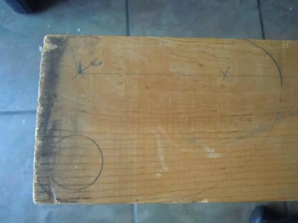
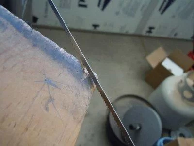
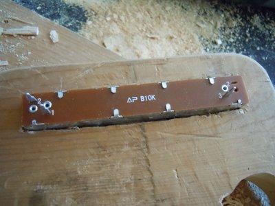
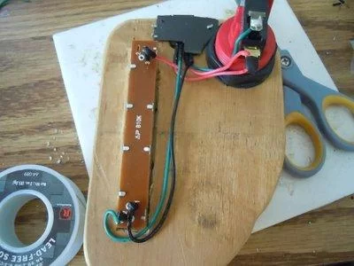
First is choosing the right shape to start off with. It all depends on how you want the controller structured. I wanted more of a flat controller so I got a piece of 3 1/2″ by 3/4″ plank. arrange the parts in a way that seems fitting and comfortable to work with. Use a french curve, compass, triangle, and straight edge to draw on where all the pieces should go. Cut the basic outline out using the cutting tool of you’re choice. A ban saw would be best but I used a coping saw, which worked just fine. Sand down the edges to make them smoothly transition, then sand down the corners to make it more comfortable.
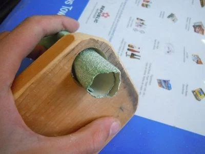
Drill out the hole for the switch, then sand,chisel, and/or Dremel out any part on the bottom that will make it fit. Try not to do anything with the top and only sand out what you need to be able to fit it in by twisting, angling, or whatever else to get it to go in. Once it is in attach it with the plastic nut and attach the switch. Drill out the area for the potentiometer knob to fit through and chisel out an area so it can sink in and fit all the way through. Drill out some holes so a screw can hold it in.
Bend in the little pieces of the USB A connector that make it’s general width increase a little (look at the pictures). Chisel out a portion for the connector, progressively checking to make sure the connector fits. Super glue the connector into it’s slot. Take a little piece of plastic and cut it into a shape that will fit over the connector (look at the pictures), and then staple it to the wood. Cut off any pieces that may get in the way. Screw in potentiometer and attach the knob.
Solder the positive wire to one of the ends of the potentiometer (not the variable portion) and the negative wire to the opposite end. Solder the D- pin to the variable pin on the pot. Solder a wire from the pin on the pot with the positive wire to one of the pins on the button. Solder D+ to the other pin on the button. Trim the spare wire and insulate the pieces that need it.
Step 6: Shirt
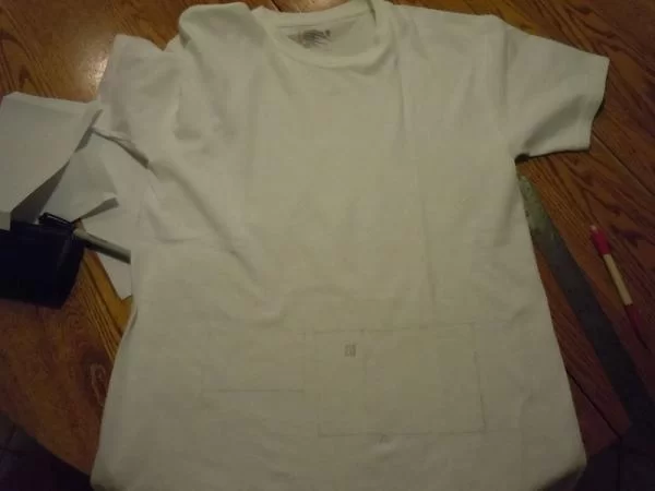

Find a comfortable shirt that will let the light through. I chose this basic white T-shirt. It doesn’t really matter the color or style as long as the light can be seen shining through from the inside. However I do not recommend graphics on the front. Lay out everything on the shirt to help you decide where you want it and use an erasable marking tool to draw it on. I (meaning some people I know) have a pencil meant for marking fabrics which washes out easily.
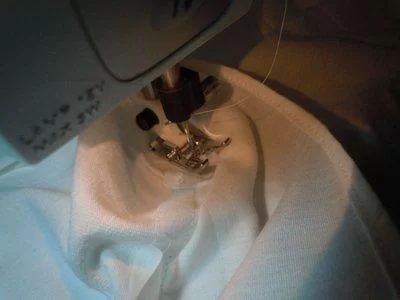
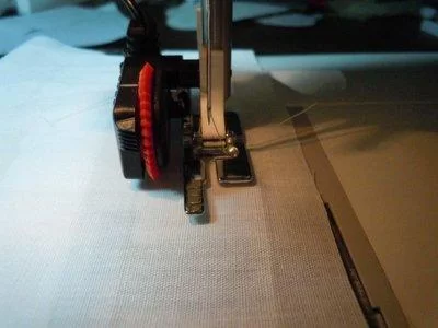
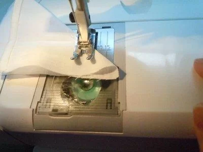
Measure the size of the batteries, controller case, and screen and cut out pieces of paper to match. Then pin the paper to a piece of non-stretchy fabric. A weave works well for this. Then cut out rectangle leaving about a quarter inch for a seam all the way around. Then using the piece of paper as a guide iron the folds into the fabric. Now the paper can be removed. On the part of the pocket that will be the top fold it over it’s self three times. Iron and pin it to keep it in place. Sew a seem all the way along the middle of the fold. Now take the corner and fold it so the un-sewn edges perpendicular to each other are parallel and sew a seem along the ironed crease closest to the corner (The pictures really help). Do this for the other corner as well.
If perchance you will have a toggle switch coming out of a pocket, sew a button hole at the base of the pocket where the switch touches. Then sew a button hole and cut out the middle portion. I can’t really give detailed instructions because I had a cool tool to make button holes. Just be sure you make the holes before the pocket is sewn on.
Take some pins and poke them through the shirt at the corners of the markings for the pocket. Take the pocket and put each corner at a pin (on the inside of the shirt), leaving a quarter inch for the seam, and pin it to the shirt. After the pocket has been pinned. remove the pins not holding the pocket in and sew the pocket to the shirt. Repeat for all the pockets. For the large pocket holding the screen leave a gap for the wires at the bottom of the pocket.
To put a hole in the shirt mark the place and take an iron on backing (with the shinier part on the fabric) and iron it on. Then, for a small hole (like what I used for the toggle switch), make a button hole. For a larger hole, mark the outline and use a zigzag stitch along the line (or curve or what-have you) and cut out the middle part.
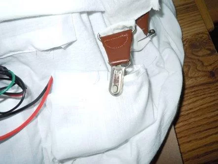
If you want you can use suspenders to hold the weight of the pockets, the two clips holding onto the pockets on the front and the back clip onto the pants. I also got a little sleeve of fabric sewn over the parts of the suspenders that will be touching my skin. Two shirts can get a little too hot so I opted out and used the little fabric sleeve.
Step 7: Programming

And here is the code. There are a few parts which are well commented but the vast majority is not. If you have questions on different parts you can either give me the line number (with #include as line number one) or give me a copy of the line(s) and the function in which it resides (like loop() or compMovePaddle()) and I will do my best to explain it to you, then add a comment to the code explaining it.
#include <Adafruit_NeoPixel.h>
#define PIN 6
//says which are the input pins for the game
int buttonPin = 40;
//dictates the score, kept in a bianary array because it is esier
int playerScore[5] = {0,0,0,0,0};
int compScore[5] = {0,0,0,0,0};
//dictates the ball’s direction
int bvd=0;//0 is down, 1 is up
int bhd=0;//0 is right, 1 is left
//dictates the balls position
int bvp = 8;
int bhp = 6;
//checks to see if the ball is in fast mode
boolean fast = false;
//checks if it is a score.
boolean cIsPoint = false;
boolean pIsPoint = false;
//paddle positions
int cPaddle = 0;
int pPaddle = 0;
long previousMillis = 0;
long previousMillisForComp = 0;
//set the delay times for fast and slow moving ball the “Int” in normInt and fastInt is for interval
int normInt = 50;
int fastInt = 10;
//used to check for a win. 1 is player win, -1 in computer win, and 0 is nothing has happend yet
int win = 0;
//to get rid of a bug. used in the addOne statement and nowhere else.
int which = 0;
//Thing displayed before start, -1 is an escape
int pongPlay[] = {1,2,3,4,10,11,12,13,16,18,20,27,29,33,34,41,42,61,62,63,70,
71,72,76,85,86,88,91,92,94,100,101,102,103,131,132,136,
139,144,145,146,147,148,161,162,166,175,183,185,192,
194,195,196,197,198,199,204,205,206,207,208,-1};
//if you win
int youWin[] = {1,2,3,4,5,16,17,18,19,20,27,33,34,39,46,47,48,49,54,55,56,57,
58,77,78,79,84,88,91,92,93,94,95,99,103,106,110,114,118,130,
131,132,144,145,146,147,151,162,163,168,169,170,177,181,192,
193,204,205,206,207,-1};
//if you lose
int youLose[] = {1,3,5,16,17,18,19,20,24,26,28, 31,32,32,33,34,35,39,46,47,48,49,
62,65,77,78,79,84,86,88,91,94,99,103,106,110,122,123,124,
130,131,132,144,148,152,153,154,162,163,168,169,170,181,192,
193,204,205,206,207,208,-1};
//sets up the led strip
Adafruit_NeoPixel strip = Adafruit_NeoPixel(210, PIN, NEO_RGB + NEO_KHZ800);
//setting up, turns no pin 40 for input, begins the strip, displays the
//message and the shows it.
void setup() {
pinMode(buttonPin,INPUT);
strip.begin();
for (int i = 0 ; pongPlay[i]>0 ; i++){
strip.setPixelColor(pongPlay[i], strip.Color(0, 0, 255));
}
strip.show();
delay(5000);
while (digitalRead(buttonPin) == LOW){
//It’s a trap!(until the button is pressed.)
}
}
void loop() {
clearScreen();
//draws the paddles to show the score
for(int i = 0 ; i < 5 ; i++){
if (playerScore[i]==1){
strip.setPixelColor(204-i, strip.Color(255, 255, 255));
}else if((playerScore[i]==0)){
strip.setPixelColor(204-i, strip.Color(0, 255, 0));
}
if (compScore[i]==1){
strip.setPixelColor(5+i, strip.Color(255, 255, 255));
}else if((compScore[i]==0)){
strip.setPixelColor(5+i, strip.Color(255, 0, 0));
}
}
//draws the ball in it’s starting position
strip.setPixelColor(98, strip.Color(255, 255, 255));
strip.show();
//decides if the ball is going up or going down
while(pIsPoint == false && cIsPoint == false){
clearScreen();
unsigned long currentMillis = millis();
//assigns the player paddle position
pPaddle=checkPaddlePos();
//checks the next position
checkNext();
//moving the ball
if (fast == false){
if(currentMillis – previousMillis > normInt){
previousMillis = currentMillis;
moveBall();
}
}else if(fast == true){
if(currentMillis – previousMillis > fastInt){
previousMillis = currentMillis;
moveBall();
}
}
//draw the ball
if(bhp%2 != 0){
strip.setPixelColor(bhp*15+14-bvp, strip.Color(255, 255, 255));
}else if (bhp%2 == 0){
strip.setPixelColor(bhp*15+bvp, strip.Color(255, 255, 255));
}
//computer paddle movement
compMovePaddle();
//draw’s the paddles
drawPaddles();
//actualy put everything up.
strip.show();
//checking to see if a point has been scored
if (pIsPoint == true){
which = 0;
bhd=0;
addOne();
break;
}else if(cIsPoint == true){
which = 1;
bhd=1;
addOne();
break;
}
}
if (win == 1){
clearScreen();
for (int i = 0 ; youWin[i]>0 ; i++){
strip.setPixelColor(youWin[i], strip.Color(255, 0, 0));
strip.show();
}
delay(5000);
for (int i = 0; i < 5; i++){
playerScore[i] = 0;
compScore[i] = 0;
}
win = 0;
}else if (win == -1){
clearScreen();
for (int i = 0 ; youLose[i]>0 ; i++){
strip.setPixelColor(youLose[i], strip.Color(0, 255, 0));
strip.show();
}
delay(5000);
for (int i = 0; i < 5; i++){
playerScore[i] = 0;
compScore[i] = 0;
}
win = 0;
}
pIsPoint = false;
cIsPoint = false;
bvp = 8;
bhp = 6;
bvd=random(0,2);//0 is down, 1 is up
fast=false;
}
//The AI for the game
void compMovePaddle(){
unsigned long currentMillis = millis();
if(currentMillis – previousMillisForComp > 51){
previousMillisForComp = currentMillis;
if (bvp >= 13 && 10-cPaddle <= 10 && cPaddle > 0){
cPaddle–;
}else if(bvp <= 0 && 10-cPaddle >= 0 && cPaddle < 10){
cPaddle++;
}else if(bvp-3 > 10-cPaddle && 10-cPaddle >= 0 && cPaddle > 0){
cPaddle–;
}else if(bvp < 10-cPaddle && 10-cPaddle <= 10){
cPaddle++;
}
}
}
//moves the ball
void moveBall(){
if (bhd == 0){
bhp–;
}else if(bhd == 1){
bhp++;
}
if (bvd == 0){
bvp–;
}else if(bvd == 1){
bvp++;
}
}
//adds one to the array. If whichOne is 0 it adds to the player’s score. If it’s 1 it adds to the computers
void addOne(){
if (which == 0){//if it’s the player’s score
//Add one. This is the simpleist way I know how.
for (int i=0 ; i < 5 ; i++){//loop
if (playerScore[i] == 0){//if that value is a zero
playerScore[i]=1;//make it 1
break;//then go away
}else {//if it is 1
playerScore[i]=0;//make it zero and loop
}
}
}else if(which == 1){
for (int i=0 ; i < 5 ; i++){
if (compScore[i] == 0){
compScore[i]=compScore[i]+1;
break;
}else {
compScore[i]=0;
}
}
}
//Checks to see if anyone won.
if (compScore[0]==1 && compScore[2]==1 && compScore[4]==1){
win = -1;
}else if (playerScore[0]==1 && playerScore[2]==1 && playerScore[4]==1){
win = 1;
}
}
//checks the balls next position
void checkNext(){
//check’s to see if a point has been scored
if (bhp == 13){
pIsPoint = true;
}else if(bhp == 0){
cIsPoint = true;
}
//if a point has been scored than skip over the rest of this stuff
if (pIsPoint == false || cIsPoint == false){
//checks the ball verticaly
if (bvp+bvd==15){
bvd = 0;
}else if(bvp+bvd==0){
bvd = 1;
}
//checks the ball horizontaly
if (bhp+bhd==13){//first on the computer side
if (bvp >= 10-cPaddle && bvp <= 10-cPaddle+4){
if(bhd==1){
bhd=0;
}else if(bhd==0){
bhd=1;
}
fast = false;
}else if(bvp+bvd == 10-cPaddle || bvp+bvd == 10-cPaddle+5){
if(bvp != 0 && bvp !=14){
if (bvd == 0){
bvd=1;
}else if(bvd == 1){
bvd=0;
}
bhd=1;
}else if (bvp == 0 || bvp == 14){
bhd=1;
}
fast = false;
}
}else if(bhp+bhd==1){//then on the player side
if (bvp >= pPaddle && bvp <= pPaddle+4){//is it hitting the paddle in a normal spot?
//bounce the ball!
if(bhd==1){
bhd=0;
}else if(bhd==0){
bhd=1;
}
}else if(bvp+bvd == pPaddle || bvp+bvd-5 == pPaddle){//is it hitting the paddle on the corner
if(bvp != 0 && bvp !=14){//is it not up high or down low?
//Bounce the ball!
if (bvd == 0){
bvd=1;
}else if(bvd == 1){
bvd=0;
}
bhd=1;
fast = true;
}else if (bvp == 0 || bvp == 14){//is it up high or down low?
//bounce the ball!
bhd=0;
fast = true;//set the value to later make the ball move fast
}
}
}
}
}
int checkPaddlePos(){
//reads the pot and decides on the paddle position acordingly
if (analogRead(A15)<93){
return 0;
}else if(analogRead(A15)<186){
return 1;
}else if(analogRead(A15)<279){
return 2;
}else if(analogRead(A15)<372){
return 3;
}else if(analogRead(A15)<465){
return 4;
}else if(analogRead(A15)<558){
return 5;
}else if(analogRead(A15)<652){
return 6;
}else if(analogRead(A15)<745){
return 7;
}else if(analogRead(A15)<837){
return 8;
}else if(analogRead(A15)<=931){
return 9;
}else if(analogRead(A15)<=2014){
return 10;
}
}
void drawPaddles(){
//draw’s the paddles in the correct spot and displays the score on the paddle
for(int i = 0 ; i < 5 ; i++){
if (playerScore[i]==1){
strip.setPixelColor(pPaddle+i, strip.Color(255, 255, 255));
}else if((playerScore[i]==0)){
strip.setPixelColor(pPaddle+i, strip.Color(255, 0, 0));
}
if (compScore[i]==1){
strip.setPixelColor(199+cPaddle-i, strip.Color(255, 255, 255));
}else if((compScore[i]==0)){
strip.setPixelColor(199+cPaddle-i, strip.Color(0, 255, 0));
}
}
}
void clearScreen(){
for(int i=0; i<=210 ; i++){
strip.setPixelColor(i, strip.Color(0, 0, 0));
}
strip.show();
}
Step 8: Finished Product

About The Author
Hassan Zaka
I am an expert in accounting and possess diverse experience in technical writing. I have written for various industries on topics such as finance, business, and technology. My writing style is clear and simple, and I utilize infographics and diagrams to make my writing more engaging. I can be a valuable asset to any organization in need of technical writing services.
Follow Us:LinkedinTwitter