Once upon a time, 2 girls greatly enjoyed walking in the rain with Light-Up umbrella.
They decided the enjoyment of this experience could be maximized by building their own pressure-activated web of LEDs to install under their Light-Up umbrella.
Thus, with the help of an Arduino Light-Up Umbrella, some 4051 multiplexers, a lot of wire and a lot of solder, they set off on their path to success.

Step 1: Materials List

Just based on size, we decided to use 24 LEDs to light our umbrella, with 8 strands of 3 LEDs each emanating out from the central hub.
We used the following materials:
1 umbrella
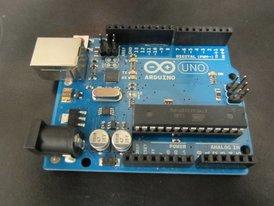
1 Arduino Uno R3 microcontroller
1 9 V Battery
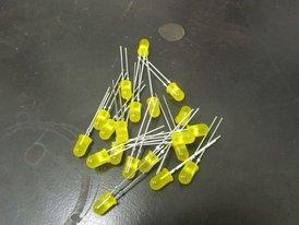
24 yellow LEDs (we advise that you use one with diffused light and a wide viewing angle, otherwise the size and color is up to you)
8 piezo sensor disks (we specifically ordered these from sparkfun: http://www.sparkfun.com/products/10293, though they are a bit fragile. You might want to look for something different.)
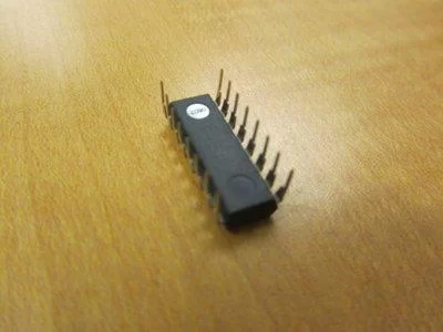
2 4051 multiplexers/demultiplexers
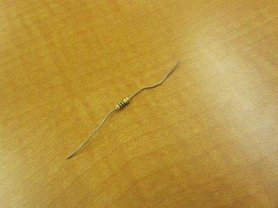
8 1 MΩ resistors (to be in parallel with the piezo sensors)
8 10 Ω resistors (to be in series with the LED strings)
LOTS of wire
LOTS of solder
Hot glue/hot glue gun
Electrical tape
Duct tape
Step 2: Program Arduino Code

Program your Arduino with the following code:
/***************************************
Pressure Activated Light-up Umbrella
by Shannon Lubetich and Emily Yang
***************************************/
int sensorReading = 0;
int r0 = 0;
int r1 = 0;
int r2 = 0;
int w0 = 0;
int w1 = 0;
int w2 = 0;
int count = 0;
void setup() {
Serial.begin(9600);
//initialize digital arduino pins as outputs to control the selecting process for our 4051 multiplexers
pinMode(2, OUTPUT); //r0
pinMode(3, OUTPUT); //r1
pinMode(4, OUTPUT); //r2
pinMode(8, OUTPUT); //w0
pinMode(9, OUTPUT); //w1
pinMode(10, OUTPUT); //w2
}
void loop(){
//cycle through each piezo disk and corresponding string of LEDs
for(int i = 0 ; i < 8; i++){
//read the analog value of the piezo disk pressure sensor
reading(i);
//send the trigger from the pressure to the LEDs
writing(i);
}
}
void reading(int sensor){
//uses binary to select the correct input to read on the 4051 multiplexer
sensorReading = 0;
r0 = bitRead(sensor, 0);
r1 = bitRead(sensor, 1);
r2 = bitRead(sensor, 2);
digitalWrite(2, r0);
digitalWrite(3, r1);
digitalWrite(4, r2);
sensorReading = analogRead(A5);
//slowly prints results to the serial monitor
count++;
if(count % 1000 == 0){
Serial.println(sensorReading);
}
}
void writing(int LED){
//uses binary to select the correct output to write to on the 4051, here used as a demultiplexer
w0 = bitRead(LED, 0);
w1 = bitRead(LED, 1);
w2 = bitRead(LED, 2);
digitalWrite(8, w0);
digitalWrite(9, w1);
digitalWrite(10, w2);
//if measured pressure above a certain threshold, trigger string of LEDs
if (sensorReading >= 15){
analogWrite(A0, sensorReading*25);
delay(125);
}
//otherwise, leave LEDs off
else{
analogWrite(A0,0);
}
}
***We were inspired by the following project, and looked at the code for it, but ended up developing our own. However, if you are interested in making an umbrella that plays musical notes due to press, this is a great page: http://whyyesihaveawebsite.com/arduino/?p=6&fb_source=message
IMPORTANT: 4051 chips are TRICKY! Take heed!
For more information about the 4051 chip, used as a multiplexer or demultiplexer, refer to Arduino playground’s page at http://www.arduino.cc/playground/Learning/4051
You should keep the schematic handy to reference all the input/output pins and where they need to be connected.
Step 3: Mock-up
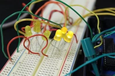
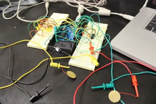
You should test out your circuit on a small scale before going crazy with wires and solder.
We did this by using 2 bread boards, placing a 4051 multiplexer/demultiplexer in each, and then connected inputs/outputs to the correct places on the Arduino.
Once again, refer to the schematic at http://www.arduino.cc/playground/Learning/4051.
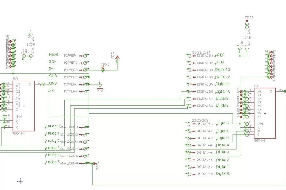
Here are some basic things to remember (all of the following pin numbers refer to the 4051 chip):
Attach the two Vcc inputs (pin 16) to the shared 5 V source of your Arduino.
Attach E (pin 6), Vee (pin 7), GND (pin 8) of both chips to the shared ground of your Arduino.
Attach z (pin 3) to an Analog In of your Arduino. If you use our exact code, attach the chip with the piezos to A5, and the chip with LEDs to A0.
Attach S0 (pin 11), S1 (pin 10), S2 (pin 9) to Digital Outputs on your Arduino. Once again, if you use our exact code, attach the chip with piezos to 2, 3, and 4, and the chip with LEDs to 8, 9, 10.
Ok! Now that you have a crazy mess of wires, you should connect your components to the remaining pins.
At first, we just wanted to make sure it worked, so we only hooked up 2 piezo sensors and 2 strings of LEDs.
These go in any of the remaining I/O pins on the 4051.
For the sensors:
Connect a wire from a 4051 pin to a piezo disk and 1 MΩ resistor, and then connect this to ground. (We advise making a shared strip of ground on your breadboard.)
For the LED strings:
Ideally, connect a wire from a 4051 pin to a resistor, and then 3 LEDs in parallel, and then to ground. (This depends largely on the types of LEDs you have- you should look at the voltage drops across them and calculate what size resistor you need in order to moderate the 5V power supply from the arduino.)
***You should hook up the LED string to the same numbered pin on the 4051 as the pin its respective piezo disk is hooked up to.
CAUTION: When we were trying to test this, we encountered some random, sporadic data. Then, we hooked up all our floating pins of the 4051 to ground, and everything worked fine. We’re not quite sure why, when the pins aren’t connected to anything, they give off random readings, but, in any case, connect every pin you’re not using to GROUND.
Now, uploading and running the Arduino code, you should be able to tap the piezo disks and then see numbers on the serial monitor, as well as see the respective LEDs lighting up.
(It’s a great feeling when this works.)
Step 4: Make a Printed Circuit Board (optional)
This step is not extremely necessary, if you don’t have the facilities to do it, but it is VERY helpful to make a printed circuit board instead of working with the mess of wires and breadboards from the mock-up.
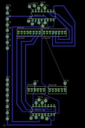
Using EAGLE software, we designed our own circuit board.
Here’s our schematic and board layout.
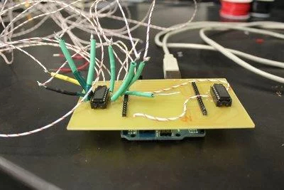
We then printed this, cut it out, drilled holes, and attached pins to attach our board to the Arduino.
The final product is really exciting and compact. So much better than the mess of breadboards, right?
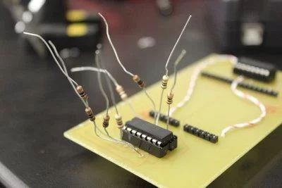
Step 5: SOLDER
NOTE: Before soldering lots and lots of wire to everything, you should measure how much wire you need. As in, figure out where you want to place your sensors and LEDs inside the actual umbrella, and how much wire you’ll need to connect them to make it there.
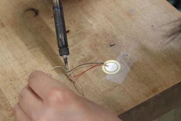
For piezo sensors:
Piezo disks in parallel with 10 MΩ resistors.
Wire to one side of resistor and pin of 4051.
Wire to other side of resistor and shared ground.
***Our piezo disks were really fragile. More like, the wires that came attached to them were really fragile and broke on us a few times. You should reinforce them with electrical tape.
For LEDs:
Resistors to pins of 4051 associated with LEDs.
Wire to resistors and LEDs.
LEDs to each other. (***make sure you hook up the LEDs in the same way, as in voltage source —> + end/ – end —> ground.)
End of LED string to shared ground.
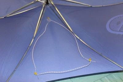
(Note: we hooked up our LEDs with 2 in parallel, and then one in series. that’s why we have cute little triangle things.)
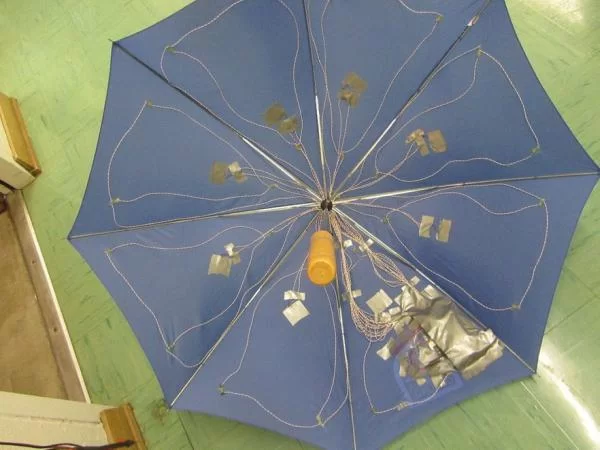
Step 6: Attach to Umbrella
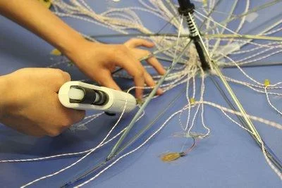
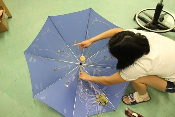
Open your umbrella, plug in your glue gun, and figure out where you want everything to be attached.
Don’t forget that you need to power your Arduino with a 9 V battery, and so you’ll need somewhere to put that in your umbrella as well.
Then, have at it. Be careful not to melt any components, or the umbrella, with the hot glue.
Also, it is helpful to hold things in place with tape while you solder. Ordinary scotch tape didn’t like to stick to our umbrella, so we ended up getting frustrated and then choosing packaging tape and duct tape, which both worked much better.
***HINT: we spread out and glued all the piezo disks first, and then turned on the Arduino, tapped the sensors, and figured out what string of LEDs corresponded, so we could attach them to the correct panel. This is IMPORTANT.
Just for ease of organizing the wires, we fed each of them from the Arduino up to the top central hub/peak of the umbrella, and then out to their respective panels. The wires get pretty messy, so we suggest taping them together and gluing them down at strategic locations so the wire doesn’t get tangled or fall off.
Step 7: Secure Electrical Connections
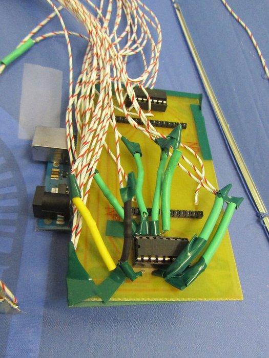
This is something we hadn’t quite anticipated, but, after running into some difficulties, realized that we desperately needed to put electrical tape on all exposed wires, so as to prevent interference between randomly touching wires.
So, we wrapped all exposed wires near each other with electrical tape as well as the soldered connection on the bottom of our shield. Our battery was previously touching some of the soldered areas, causing interference, but all we needed to do was cover the connections with electrical tape, THEN attach the 9 V battery, and we were good to go!
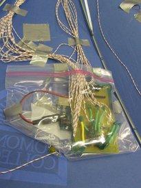
We then placed the Arduino, shield, and battery in a plastic bag to semi-waterproof it. We took this pouch and attached it to our umbrella with a ridiculous amount of duct tape.
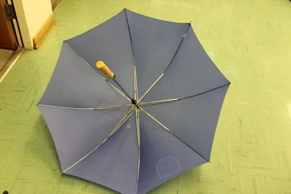
Step 8: Singin’ in the Rain


Now, wait for the rain, and go show off the BEST thing ever that will make all the neighbors jealous (especially at night). Yay!
And, if you like, you should name your umbrella. We suggest a name that rhymes with “umbrella” and means “star.” (Hint: It’s Stella. Stella the Umbrella.)
About The Author
Hassan Zaka
I am an expert in accounting and possess diverse experience in technical writing. I have written for various industries on topics such as finance, business, and technology. My writing style is clear and simple, and I utilize infographics and diagrams to make my writing more engaging. I can be a valuable asset to any organization in need of technical writing services.
Follow Us:LinkedinTwitter