Who wants grinning faces and candles when you can have an interactive Tetris pumpkin this Halloween? Play your favorite block-stacking game on an 8×16 grid carved into the face of the gourd, lit by LEDs and using the stem as a controller.

This is a moderately advanced project and requires experience soldering and programming in the Arduino environment. You’ll be working with organic matter and all its inherent quirks, so measurements may need to be adapted to fit the Tetris pumpkin you’re using.
[mom_video id=’8PCp5xk-9Qo’]Step 1: Required Materials

To build your own Pumpktris you’ll need the following:
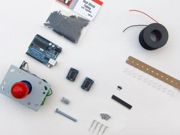
Components
- 128 5mm amber LEDs (I used these from Mouser)
Buy some extra to cover any mistakes or tests. I got 140. Amber most closely resembles the flame that would be inside a traditional jack-o-lantern, but you’re free to use any color you like. - Arduino microcontroller
- 1/16″ Heat shrink tubing (11 feet, or 256 1/2″ long pieces)
- Arcade joystick with a removable handle (this one from SparkFun worked well for me)
- 4 #6 nylon drywall anchors
This isn’t the kind with the toggles, but the kind that look like screws with deep threads - 4 half-inch long screws of the same size and type that came with the drywall anchors.
The ones that come with the anchors will be too long. - 6mm x 50mm bolt (or whatever size matches the mount for your joystick handle)
- 6mm coupling nut (or whatever size is needed to match the above bolt)
A coupling nut looks like a regular nut, but is about an inch long and is used to join two bolts or pieces of threaded rod.
And last but not least, you’ll need 1 pumpkin. You only need one, but I recommend two so that you’ve got one you can use to practice drilling and cutting. Your LED matrix is going to cover an area approximately 4″ wide by 8″ tall, so you want a pumpkin with an area that size as smooth and flat as possible so your matrix doesn’t wrap too far around. You could use a foam pumpkin, but where’s the magic in that? I can’t speak to the carving techniques needed on a foam pumpkin.
Tools and Consumables
- Soldering iron
- Solder
- Wire cutters
- Wire strippers
- Power drill
- Hacksaw
- X-Acto knife
- 13/64″ drill bit
- 1-1/8″ drill bit (I used a Forstner bit, but a spade bit might work too)
- 1/4″ foam core board
Step 2: Building an LED Matrix
You’ll start by building sixteen eight-segment daisy-chains of wires—each with 7 short and 1 long wire. Twist each end together with the next piece and solder.
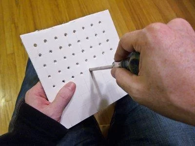
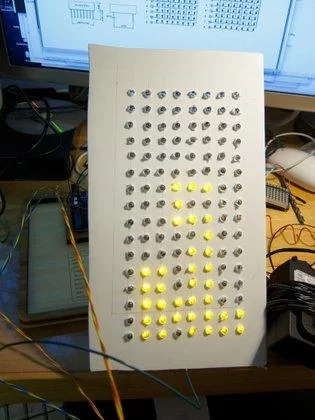
To connect the wires to the LEDs you’ll need a jig to hold the LEDS. Draw an 8×8 grid with half-inch spacing on a piece of 1/4″-thick foam-core board, then use an awl to poke a hole slightly smaller in diameter than the LED at each intersection. You’ll have 64 holes when you’re done.
In the top row of holes insert 8 LEDs. The foam-core will stretch to fit the LEDs and will hold them tightly. Align the LEDs so the longer leg—the anode lead— is facing toward you on each. Double-check, because if you get one wrong the matrix won’t work.
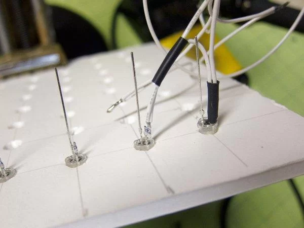
Clip each anode lead to about 1/4″ long, and tin it with solder to make it easier to connect the wires.
Cut 8 pieces of heat-shrink tubing into 1/2″ segments. Slide a piece of tubing over the first wire connection, push it back so it’s not affected by the heat of the solder, then solder the wire connection to the LED anode. Slide the tubing down over the connection once it’s cooled. Continue on to the next LED, repeating seven more times the process of sliding on a piece of tubing, soldering the connection, then lowering the tubing over the joint.
When you’ve got a set of eight LEDs all connected to each other, remove them from the jig and repeat again for seven more rows, being sure to make all connections to the anode lead of each LED. You can use whichever row of the jig is easiest to reach, since you’re only working with one at a time.
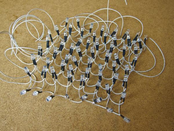
After all eight rows have been soldered, it’s time to join the columns and make a matrix.
Insert all of the LED strings into the jig you made. Keep the long wire on the same side of each string.
Cut and tin the cathode lead of each LED in the first column, just like you did to build the string. Take another wire chain and repeat the process of soldering it to the LEDs, only this time you’re connecting it at 90 degrees to the first set of wires you did. Keep the long wire on the same side of the matrix.
As you complete each column, remove it from the foam-core jig and fold it out of the way to provide access to the next column.
When you’re all done you’ll have 64 LEDs joined in 8 rows and 8 columns. Unfortunately, you need to repeat the process again for the second matrix. If you need a break, skip to steps 3, 4, and 5 to work on the code, then come back to this.
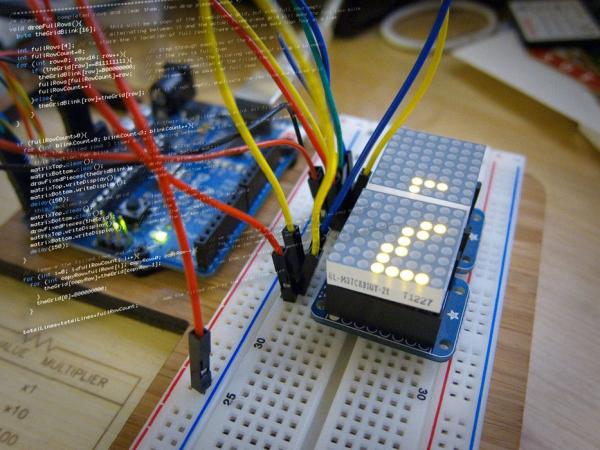
Step 3: Controlling the LEDs
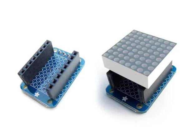
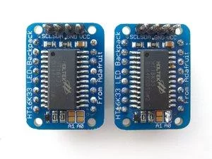
The LED matrices you’ve made will be controlled by two Mini 8×8 LED Matrix Backpacks from Adafruit. Each controller allows you to drive 64 LEDs with only two wires from the Arduino, and you can chain multiple controllers together on those same two wires.
Follow the directions that come with the LED Matrix Backpack to solder on the 4-pin power/data/clock header. Then, instead of soldering on the LED matrix that comes with it, solder two rows of female headers to the backpack. Plug the included mini LED matrix into the headers.
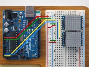
Plug the matrix into a breadboard and connect it as follows:
- Connect CLK pin on the Backpack to analog pin 5 on the Arduino.
- Connect the DAT pin to analog pin 4 on the Arduino.
- Connect GND to the ground pin on the Arduino.
- Connect VCC+ to 5v power.
Download the Adafruit LED Backpack library and Adafruit GFX libraries and install them on your computer by copying each to the “libraries” folder of your computer’s Arduino sketch folder. Upload the “matrix8x8” file to your Arduino and verify that the LED backpack is working. The pins of the LED matrix might not make good contact in the female headers, so you may need to wiggle or partially remove it in order to make contact and allow all rows and columns to light.
Repeat the process with the second LED backpack, but this time you’ll need to set a new address for it by soldering a jumper across the A0 pads on the backpack. Run the “matrix8x8” code again, but change the line “matrix.begin(0x70)” to “matrix.begin(0x71)” so that the code addresses the new LED backpack.
Step 4: Connecting the Joystick
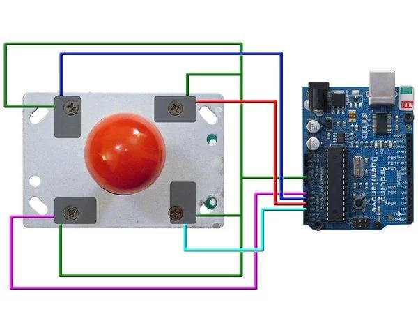
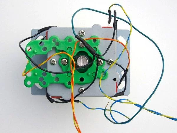
Your joystick should have four switches with two terminals each. When you move your joystick to the right it triggers the switch on the left, when you move it down it triggers the switch on top, and so on.
On one terminal of each switch, solder a 3″ wire. Twist the other end of all four of these wires together and solder them to a 12″ wire. This is the common ground for all four switches.
Solder a 12″ wire to the remaining terminal of each switch, then connect them as follows:
- Connect the bottom switch (activated when you push up) to analog pin 0 on the Arduino.
- Connect the left switch (activated when you push right) to analog pin 1 on the Arduino.
- Connect the top switch (activated when you push down) to analog pin 2 on the Arduino.
- Connect the right switch (activated when you push left) to analog pin 3 on the Arduino.
- Connect the common ground wire to the ground pin on the Arduino.
Step 5: Programming the Game
Describing the Shapes
There are seven tetrominos, each with 4 pixels, and each with four possible rotations. We store all of this in a multi-dimensional array: the first dimension consisting of the seven shapes, the second dimension containing the four rotations for each shape, the third containing four pixel descriptions that each consist of an X and Y coordinate.
For example, this describes the “T” shape:
/* T */ {
/* angle 0 */ { {0,1}, {1,1}, {2,1}, {1,2} },
/* angle 90 */ { {1,0}, {1,1}, {2,1}, {1,2} },
/* angle 180 */ { {1,0}, {0,1}, {1,1}, {2,1} },
/* angle 270 */ { {1,0}, {0,1}, {1,1}, {1,2} }
}
Tracking the Active Piece
To keep track of the piece currently in play, the program maintains an activePiece variable. This is the index of the active shape in the highest level of the array. It also keeps a rotationvariable containing the index of the current rotation. An xOffset variable tracks how far left or right (0-7) each piece is, and yOffset tracks how far down (0-15) the board it’s fallen. To draw the active piece the program adds the X and Y offset values to the X and Y coordinates of each pixel pulled from the current rotation of the selected piece.
Tracking the Fixed Pieces
The program uses a 16 byte array to keep track of the fixed pieces, with each byte representing a row. For example, the array below would represent an L shape sitting in the center of the bottom two rows (as indicated by the 1s in the last two bytes):
{
B00000000,
B00000000,
B00000000,
B00000000,
B00000000,
B00000000,
B00000000,
B00000000,
B00000000,
B00000000,
B00000000,
B00000000,
B00000000,
B00000000,
B00100000,
B00111000
};
Collision Detection
When an attempt is made to move the active piece, the program first checks the new position against the array of fixed pieces. If there are no collisions, the move is allowed and the matrix is redrawn. If a collision is detected while attempting to move left, right, or to rotate, the action is prohibited. If a collision is detected while attempting to drop a piece, the piece becomes fixed in its position and is added to the array of fixed pixels.
Dropping Pieces Automatically
The pace of the game is controlled by the gravityTrigger and stepCounter variables. Every loop of the program increments stepCounter, and every time stepCounter reaches the count stored in gravityTrigger, it drops the active piece one level.
As the game progresses, gravityTrigger is decreased so that the active piece drops more and more frequently until finally it’s dropping in every loop of the program.
Every time an active piece is fixed to the grid the program checks for full bytes/rows (B11111111). If it finds any, it blinks them off and on three times, then removes them and drops the rows above to fill the gap.
Troubleshooting
If the pieces aren’t falling from top to bottom, but instead go from side to side, change the value passed in the lines “matrixTop.setRotation(1);” and/or “matrixBottom.setRotation(1);” in the “setup()” loop.
If the pieces start in the wrong matrix, switch the physical location of each matrix or reverse the addresses declared in the “matrixTop.begin(0x70);” and “matrixBottom.begin(0x71);” lines of the “setup()” loop.
If some rows or columns don’t light, wiggle the mini LED matrix in the female headers. They may not be making good contact.
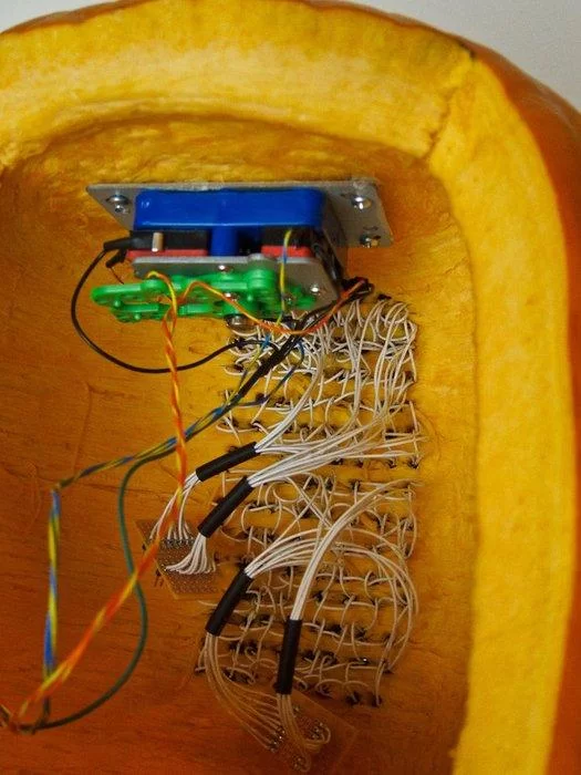
Step 6: Connecting Your LED Matrix
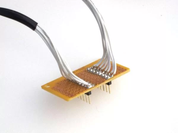
You could plug each wire into the headers on the matrix backpack individually, but you’ll probably be doing a lot of plugging and unplugging, so that could get to be a real hassle. Instead you want to solder each wire onto a male header strip and plug that into the matrix backpack. I mounted the header strips on a piece of prototyping board so I could plug and unplug all 16 pins together.
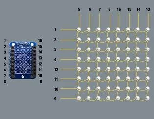
Rows 1-4 connect to pins 1-4 on the matrix backpack (pin numbering starts at the top left as you’re looking down on the backpack with the 4-pin power/ground/data/clock pins on top). Columns 1-4 connect to pins 5-8. The pin numbering wraps around so that pin 9 is on the bottom right. Rows 5-8 connect to pins 12-9, and columns 5-8 connect to pins 16-13. See the diagram for more clarity.
Plug each matrix into a backpack and run the same “matrix8x8” program that you did for the mini LED matrices in step 4. If each works, then you can load the game program. If it doesn’t work, check that the rows and columns of the large LED matrix are plugged into the correct pins of the backpack. Mounting the LED matrix in the foam-core jig you made for assembly can make it easier to test the entire system.
Step 7: Carving the Pumpkin

Don’t do any carving on the pumpkin until all of your electronics are working. A carved pumpkin has a limited shelf life, and if you carve it first and then spend 2 days on the electronics, that’s two days of game-playing fun you’ve lost.
Find the flattest side on the pumpkin so that your LED panel doesn’t wrap too far around, then cut an opening on the side opposite that. Be generous; you’re going to need room to get your hands in there to work. You’re not going to cut the top like on a traditional pumpkin because that needs to be left intact for the joystick. Pumpkin goo and electronics are not the best of friends, so clean the inside well.
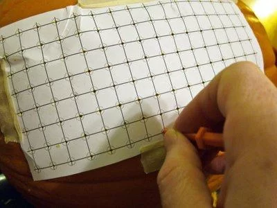
For the best-looking Pumpktris you want your grid of LEDs to be straight and well-aligned with the pumpkin. A PDF is attached with 8×16 spacing, half an inch apart. Print this (or make your own with your own spacing), cut around the edges, and tape it onto the front of the pumpkin. Be sure that it’s straight up and down.
With a nail, toothpick, or other similar tool, poke a pilot hole into the center of each LED marked on the paper. Drilling directly through the paper isn’t advised because it’s likely to shift or tear.
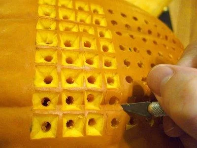
Once all of the pilot holes have been poked, remove the paper template and use a 13/64″ bit in your power drill to drill each hole. Do not align the drill perpendicular to the face of the pumpkin! If you do this, the curvature of the pumpkin may cause holes that are half an inch apart on the outside to meet on the inside and it’ll be difficult to insert the LEDs. Instead try to keep all of the holes parallel.
When all of the holes are drilled, use your X-Acto knife to cut a square “pixel” around each hole. Angle the knife toward the center of each hole and leave about 1/8″ between pixels.
I suggest buying a practice pumpkin and using it to perfect your drilling and pixel-carving technique. Master it there before you take a chance on ruining the perfect pumpkin you found for the finished product.
Step 8: Mounting the Stem to the Joystick
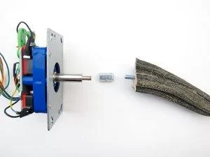
Now you’ll adapt the stem to be used as a joystick to control the game.
Cut the stem off as close to the base as possible. If the cut isn’t smooth and clean, use a sanding block to flatten it.
Drill a 1-1/8″ hole straight through the base of the stem and into the pumpkin.
Unscrew the ball of the joystick and align the shaft with the center of the hole from the inside of the pumpkin. Be sure that the front of the joystick is square with the front face of the pumpkin—when you play you want to be pushing left and right to move pieces, not at an angle. When it’s centered and square, use a nail or toothpick to poke holes into the inside of the pumpkin above the mounting holes in the joystick base.
Remove the joystick. With your wire cutters, cut the expanding tips off of the drywall anchors so that they’re shorter than the thickness of the pumpkin’s skin. Screw these shortened, snubnose drywall anchors into the pilot holes you made.
The details of the next part will depend on the joystick you bought. The one I used from SparkFun had a 6mm attachment for the ball handle that’ll be replaced by the stem. If your joystick is different, use whatever size nuts and bolts match.
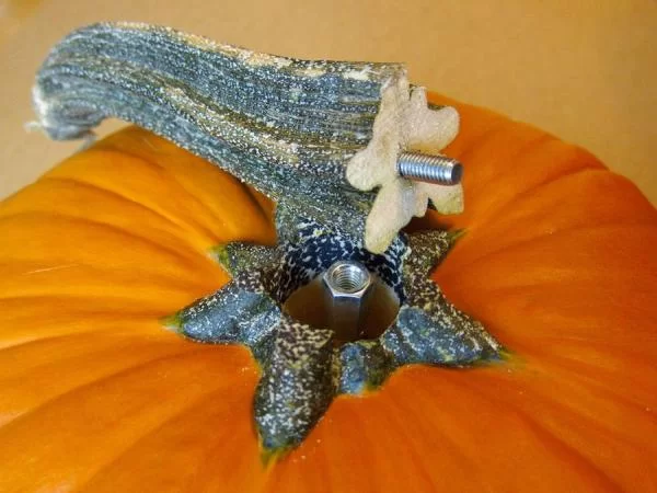
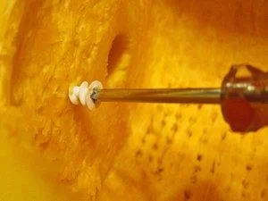
Find the center of the stem and drill a 13/64″ hole (the same size you used for the LED holes, coincidentally) about an inch straight into the stem. This would be a good step to test on your practice pumpkin, to make sure the bolt screws tightly into the hole.
Cut the head off of a 6mm x 50mm bolt with a hacksaw. Put epoxy or wood glue onto the threads near the cut end of the screw, and screw it into the stem. You want an inch or so of it in the stem and an inch outside.
Screw the 6mm coupling nut onto the joystick shaft, but don’t mount the joystick in the pumpkin yet.
Step 9: LED and Joystick Placement
Add a layer of plastic wrap to the top of the joystick, with the shaft itself poking through. This will keep at least some moisture from seeping into it. Attach the joystick with 1/2″ screws into the drywall anchors. The screws that came with the anchors will be too long and would poke through the pumpkin.
Step 10: Playing the Game

Ideas for Further Exploration
Instead of mounting the joystick on the top of the pumpkin with the LEDs, you could use a remote pumpkin, either wirelessly or with a cable decorated to look like a vine.
Instead of a game, you could display scrolling messages on your jack-o-lantern. You might want to mount the matrices sideways (16 wide by 8 high), or even use only one matrix.
The Inevitable Decay
Your pumpkin will eventually begin to rot and sprout mold and fungus. This could be dangerous to your health and could lead to glitches in your electronics. It’s best to pull out all of your electronics once you see any growth on or in the pumpkin, so that you’re able to re-use them later without requiring a Haz-Mat cleanup.
About The Author
Hassan Zaka
I am an expert in accounting and possess diverse experience in technical writing. I have written for various industries on topics such as finance, business, and technology. My writing style is clear and simple, and I utilize infographics and diagrams to make my writing more engaging. I can be a valuable asset to any organization in need of technical writing services.
Follow Us:LinkedinTwitter