The first step of building the Raspberry Pi-powered speaking doorbell is building a simple input circuit. The purpose of the input circuit is to protect the Pi from damage by electrically isolating the doorbell and its power supply from the Raspberry Pi itself.
The circuit design and a full description of how it works can be found here. The power supply I used is rated at 12V, but the LTV-847 optocoupler used in the design copes just fine with an input voltage of 12V. It is a 4 channel optocoupler, so you can read 4 different inputs using the same optocoupler. I like using veroboard / stripboard for my circuits because the soldered connections are a bit more robust than a breadboard setup.

On the left are the 2 single-core cables that are connected to my doorbell and its 12V power supply. The + (anode) of the 12V power supply is wired to my doorbell button which in turn is connected to the input circuit (top left cable). The bottom-left cable on the input circuit is then connected to the – (cathode) of the power supply.
On the right-hand side, you’ll notice a ribbon cable. I have a model B Raspberry Pi, which has a 26 pin P1 header. I bought a 26pin IDC crimp connector and some ribbon cable, which fits perfectly on the P1 header.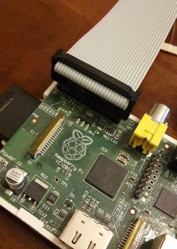
The red cable indicates Pin 1 on the Raspberry Pi, so in the input circuit picture, the top right cable is connected to the 22nd cable of the ribbon cable (which corresponds to pin 22 on the Raspberry Pi) and the bottom-right cable is connected to the 20th cable (pin 20 on the Pi).
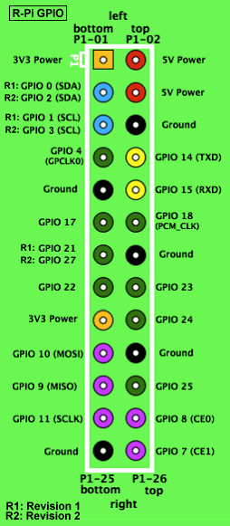
As you can see from the pin mapping diagram, pin 22 is GPIO 25 and pin 20 is Ground.

You’ll notice on the bottom view of the input circuit that the tracks on the stripboard is scratched off between the input and output sides of the optocoupler. It is a good idea to test with a multimeter to make sure there is no continuity when measuring on either side of the “break” in the track to be sure that the connection is properly broken.
If you are like me and your soldering skills are not great, I would recommend testing the circuit before connecting it to your Pi. Get a friend to press your doorbell button while you measure continuity on the output side of the optocoupler – when the doorbell is pressed, the output side should be closed. When it is not pressed, it should be open.
I also like to test to make sure there is no continuity between consecutive tracks on the stripboard to make sure I didn’t accidentally solder a connection between tracks.
Source: The Raspberry Pi Powered Speaking Doorbell – Part 1: The Input Circuit
About The Author
Hassan Zaka
I am an expert in accounting and possess diverse experience in technical writing. I have written for various industries on topics such as finance, business, and technology. My writing style is clear and simple, and I utilize infographics and diagrams to make my writing more engaging. I can be a valuable asset to any organization in need of technical writing services.
Follow Us:LinkedinTwitter