Hi, everyone, i would like to introduce how i remake my mosquito killer here. With this remaking, my mosquito killer become “Smart”, and really facilitate my life.
I rented a room in very remote place to save my money, in the summer, the biggest trouble I come across, is the mosquito killer.These annoying mosquitoes always woke me up in the middle of the night and bite me scarred. So, I bought an electric mosquito coil to drive them away. But I found that my electric mosquito coil runs fast very soon because I always forget to turn it off when I wake up in the morning.
This is not only a problem of money, but also harmful to my health. I don’t know if this “Mosquito killer” will kill me too if i stay in the room with this killer on all the time.
And as I know, usually the mosquito do not trouble me in the daytime, and, if the temperature is not so high, the mosquito sleeps in home and do not trouble me, too.
So, I need something to
1. Turn off my electric mosquito coil in the morning and turn it on in the night automatically,
2. When the temperature is low, turn off the electric mosquito coil, to save money and my health.
As a software engineer and Arduino lover, I decide to make such a device.
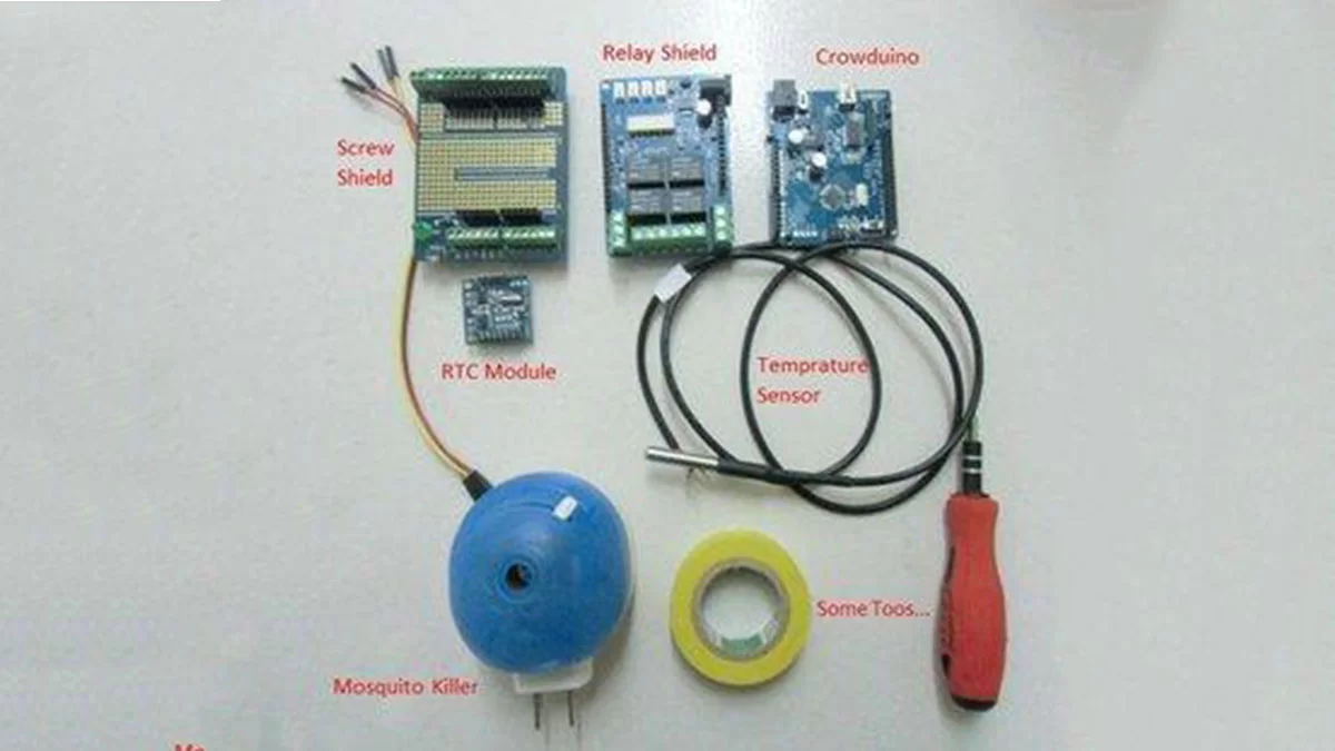
First, I need:
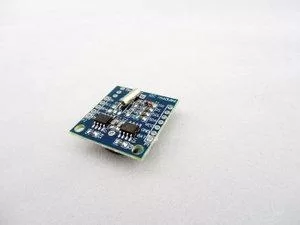
1. A RTC module, to give out the current time message.RTC is a “real time-clock”, and gives the real time to the system: ”hey, man, it’s time to wake up! ”
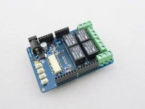
2. A Relay shield, to control the on/off of my electric mosquito coil,“Relay” is a kind of module to help you control the on/off of large current/high voltage device, with low voltage.
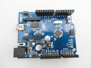
3. An Arduino board, i use the crowduino from elecrow, it works well, and, inexpensive.
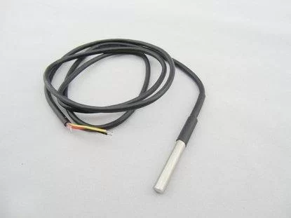
4. A Waterproof temperature sensor, to detect the environment temperature.I use this sensor to get the temperature, when the temperature is low, the killer should not be on.
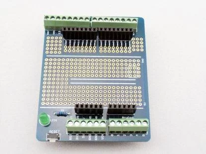
5. A Screw shield and some tools like the pliers, to make your connection more convenience.With the screw shield, it would be easy for you to connect the wires, you do not a soldering iron any more.
All parts are buy form Elecrow, an open hardware store, all parts are work nice and the price is cheap enough.
Step 1: Connect the Temperature Sensor to the Screw Shield
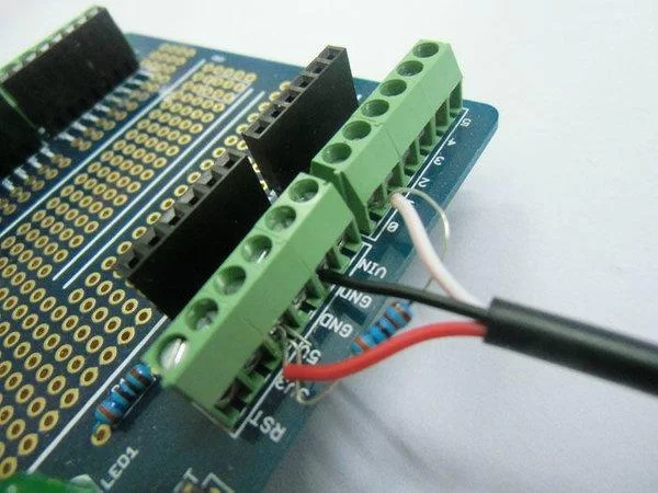
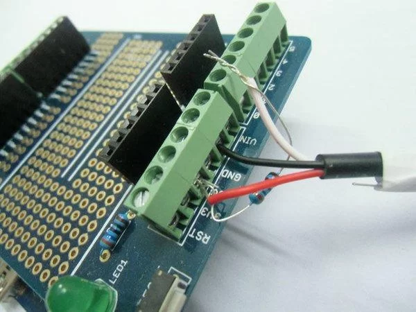
Ok, let’s go! The first step is connecting the temperature sensor to the screw shield. Just as the picture shows, a resistor is needed here. Connect a 4.7k resistor in parallel to the red and white pins of the temperature sensor( thanks to the carefulness of elecrow , this resistor was packaged with the temprature sensor) . Then, connect the wires to the screw shield as in the picture.
The three wires of the temperature sensor definition are:
VCC<->RED;
GND<->BLACK;
SIGNAL<->WHITE;
Step 2: Connect the RTC Module to Screw Shield
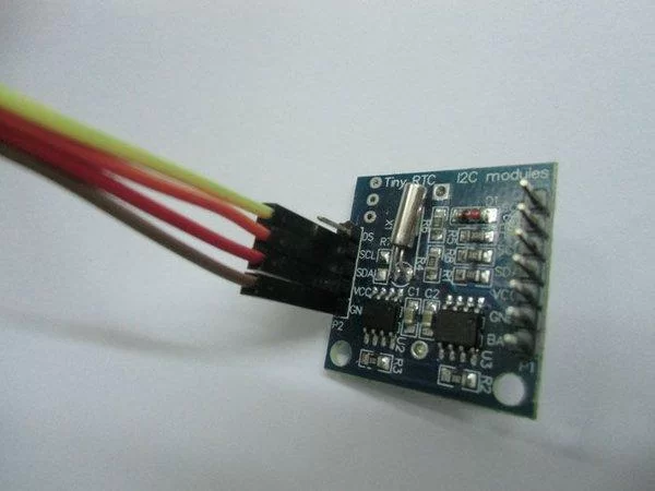
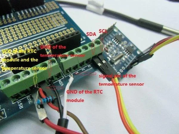
The second step is to connect the RTC module, we need this module to supply us the time information. I do not need to worry about the driver of this module, there is already a library to operating this module. In addition, we only use this module to supply time information, so we just need to use 4 pins: VCC, GND SDA, SCL.
Follow the picture to connect the RTC module to the screw shield. And, don’t forget to install a battery to the RTC module.
As the time setting, please refer to the comment in the code to learn how to set the current time.
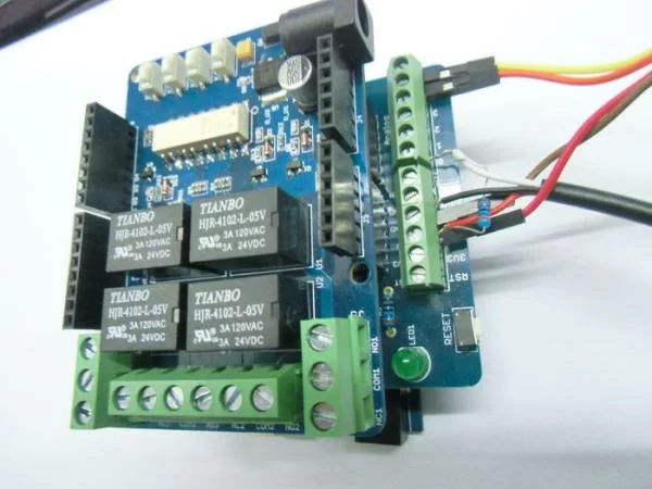
Step 3: Connect the Shields
Step 4: Refitting the Electronic Liquid Vaporizer

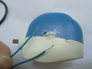

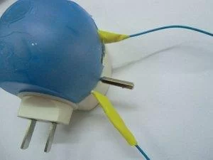
In the end, I have to using violence to take it apart, sorry, my liquid vaporizer… Just like the picture, lead out the power wire and cut it off, then using two jumper wire to connect the power wire, using the insulation paste to tangle on the wire. Finally, using insulation paste to sealing the wound of the liquid vaporizer. I think with this paste, the wound could cure soon, and it is nice too…
Step 5: Connect the Liquid Vaporizer to the Relay Shield
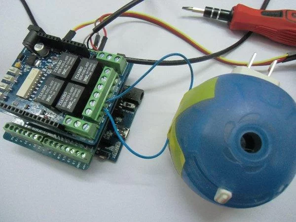
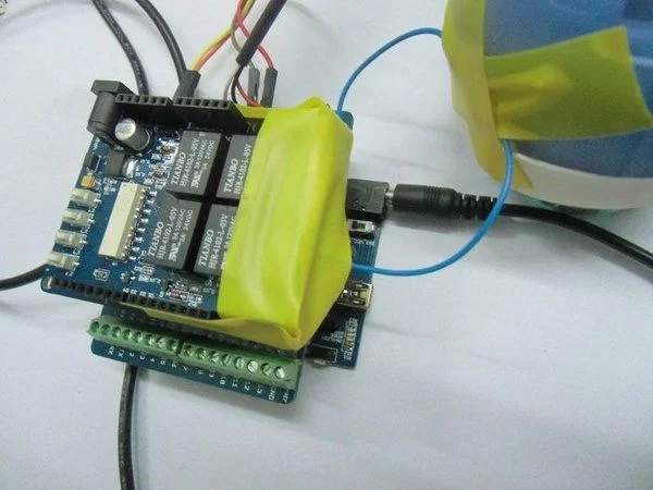
This step is to connect the liquid vaporizer to the Relay shield, Relay shield acts as a “low voltage controlled switch to control high voltage”. Please note that the high voltage may cause some dangerous.
Plug the two wires of liquid vaporizer to the terminal COM3 and NO3 of the Relay Shield, using screw driver to tightening it. In order to avoid touch the terminal accidentally, I paste some insulation paste to wrapped up the terminal of the relay shield. After this, I don’t have to worry about waking up in the mid-night and touch the relay shield accidentally.
Step 6: Programming
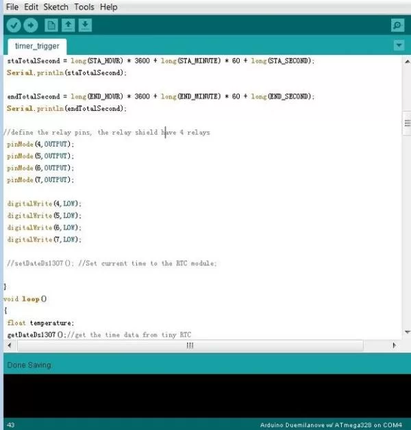
See the picture one, you can define the work time, current time and the trigger temperature in the first several lines.
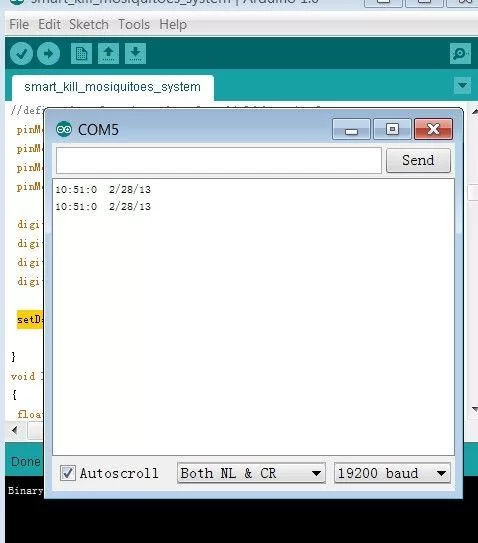
For the RTC module, you need to initialize it to setting its current time. Please see the picture 1, in the setup(), run the setDateDs1307(); //Set current time to the RTC module; this function is only need to run one time, after you setting the current time, you need to comment that line and re-upload the program to your arduino. You can see the RTC time in the monitor window.
Here is the code of this project, you can download the attachment in the below, or just simply cope the code in the below to your Arduino IDE, and upload to the crowduino.
#include “Wire.h”
#define DS1307_I2C_ADDRESS 0x68 // the I2C address of Tiny RTC
//define the start time, for example, I want to monitoring start at 22:00:00
#define STA_HOUR 22
#define STA_MINUTE 00
#define STA_SECOND 0
//define the end time, stop monitoring at 6:30:00
#define END_HOUR 6
#define END_MINUTE 30
#define END_SECOND 0
//define the current time, you can configure the current time in here
#define CURRENT_SECOND 0
#define CURRENT_MINUTE 0
#define CURRENT_HOUR 12
#define CURRENT_DAYOFWEEK 3
#define CURRENT_DAYOFMONTH 16
#define CURRENT_MONTH 3
#define CURRENT_YEAR 2013
//define the trigger temperature, only the temperature higher than 22, the relay will trigger in the specify time
#define TRIGGER_TEMPERATURE 22
OneWire ds(14); // on pin 14 for temperature
boolean flag; //To recorde the state of the temperature sensor
byte second, minute, hour, dayOfWeek, dayOfMonth, month, year;
long staTotalSecond, endTotalSecond, currentTotalSecond;
// Convert normal decimal numbers to binary coded decimal
byte decToBcd(byte val)
{
return ( (val/10*16) + (val%10) );
}
// Convert binary coded decimal to normal decimal numbers
byte bcdToDec(byte val)
{
return ( (val/16*10) + (val%16) );
}
void setup() {
Wire.begin();
Serial.begin(19200);
flag = true;
staTotalSecond = long(STA_HOUR) * 3600 + long(STA_MINUTE) * 60 + long(STA_SECOND);//to caculate the total seconds
//Serial.println(staTotalSecond);
endTotalSecond = long(END_HOUR) * 3600 + long(END_MINUTE) * 60 + long(END_SECOND);//to caculate the total seconds
//Serial.println(endTotalSecond);
//define the relay pins, the relay shield have 4 relays
pinMode(4,OUTPUT);
pinMode(5,OUTPUT);
pinMode(6,OUTPUT);
pinMode(7,OUTPUT);
digitalWrite(4,LOW);
digitalWrite(5,LOW);
digitalWrite(6,LOW);
digitalWrite(7,LOW);
setDateDs1307(); //Set current time to the RTC module,
//this code is only need run one time, after setting the current time successfully, pleas comment this line.
}
void loop()
{
float temperature;
getDateDs1307();//get the time data from tiny RTC
currentTotalSecond = long(hour) * 3600 + long(minute) * 60 + long(second);
// Serial.println(currentTotalSecond);
if(currentTotalSecond > endTotalSecond && currentTotalSecond < staTotalSecond)// to judge whether the current time in the term of setting
{
digitalWrite(5,LOW);//relay off
}
else
{
temperature = getTemperature(‘c’);//to get the teperature
if (flag)
{
Serial.println(temperature);
if(temperature > TRIGGER_TEMPERATURE)//if temperature higher than setting temperature, relay on
{
digitalWrite(5,HIGH);//relay on
}
else
{
digitalWrite(5,LOW);//relay off
}
}
}
delay(60000);//detect the time and the temperature each 60 seconds
}
// Function to set the currnt time, change the second&minute&hour to the right time
void setDateDs1307()
{
second =00;
minute = 51;
hour = 10;
dayOfWeek = 5;
dayOfMonth =28;
month =2;
year= 13;
Wire.beginTransmission(DS1307_I2C_ADDRESS);
Wire.write(decToBcd(0));
Wire.write(decToBcd(second)); // 0 to bit 7 starts the clock
Wire.write(decToBcd(minute));
Wire.write(decToBcd(hour)); // If you want 12 hour am/pm you need to set
// bit 6 (also need to change readDateDs1307)
Wire.write(decToBcd(dayOfWeek));
Wire.write(decToBcd(dayOfMonth));
Wire.write(decToBcd(month));
Wire.write(decToBcd(year));
Wire.endTransmission();
}
// Function to gets the date and time from the ds1307 and prints result
void getDateDs1307()
{
// Reset the register pointer
Wire.beginTransmission(DS1307_I2C_ADDRESS);
Wire.write(decToBcd(0));
Wire.endTransmission();
Wire.requestFrom(DS1307_I2C_ADDRESS, 7);
second = bcdToDec(Wire.read() & 0x7f);
minute = bcdToDec(Wire.read());
hour = bcdToDec(Wire.read() & 0x3f); // Need to change this if 12 hour am/pm
dayOfWeek = bcdToDec(Wire.read());
dayOfMonth = bcdToDec(Wire.read());
month = bcdToDec(Wire.read());
year = bcdToDec(Wire.read());
Serial.print(hour, DEC);
Serial.print(“:”);
Serial.print(minute, DEC);
Serial.print(“:”);
Serial.print(second, DEC);
Serial.print(” “);
Serial.print(month, DEC);
Serial.print(“/”);
Serial.print(dayOfMonth, DEC);
Serial.print(“/”);
Serial.print(year,DEC);
Serial.print(” “);
Serial.println();
//Serial.print(“Day of week:”);
}
//get the temperature, the paremeter is a char, if it equal to ‘f’, return fahrenheit,else return celsius
float getTemperature(char unit)
{
byte i;
byte present = 0;
byte type_s = 0;
byte data[12];
byte addr[8];
float celsius, fahrenheit;
if ( !ds.search(addr)) {
// Serial.println(“No more addresses.”);
// Serial.println();
ds.reset_search();
delay(250);
flag = false;
return 0;
}
else
flag = true;
if (OneWire::crc8(addr, 7) != addr[7]) {
// Serial.println(“CRC is not valid!”);
return 2;
}
// Serial.println();
// the first ROM byte indicates which chip
switch (addr[0]) {
case 0x10:
type_s = 1;
break;
case 0x28:
type_s = 0;
break;
case 0x22:
type_s = 0;
break;
default:
return 3;
}
ds.reset();
ds.select(addr);
ds.write(0x44,1); // start conversion, with parasite power on at the end
delay(1000); // maybe 750ms is enough, maybe not
// we might do a ds.depower() here, but the reset will take care of it.
present = ds.reset();
ds.select(addr);
ds.write(0xBE); // Read Scratchpad
for ( i = 0; i < 9; i++) { // we need 9 bytes
data[i] = ds.read();
}
// convert the data to actual temperature
unsigned int raw = (data[1] << 8) | data[0];
if (type_s) {
raw = raw << 3; // 9 bit resolution default
if (data[7] == 0x10) {
// count remain gives full 12 bit resolution
raw = (raw & 0xFFF0) + 12 – data[6];
}
} else {
byte cfg = (data[4] & 0x60);
if (cfg == 0x00) raw = raw << 3; // 9 bit resolution, 93.75 ms
else if (cfg == 0x20) raw = raw << 2; // 10 bit res, 187.5 ms
else if (cfg == 0x40) raw = raw << 1; // 11 bit res, 375 ms
// default is 12 bit resolution, 750 ms conversion time
}
celsius = (float)raw / 16.0;
fahrenheit = celsius * 1.8 + 32.0;
if (‘f’== unit)
return fahrenheit;
else
return celsius;
}
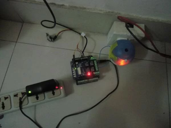
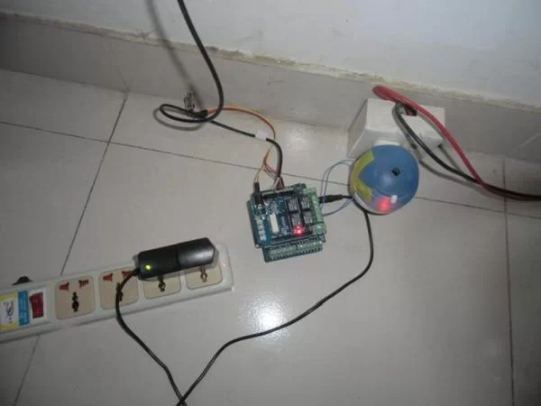
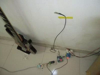
Step 7: Install and Test the System

About The Author
Hassan Zaka
I am an expert in accounting and possess diverse experience in technical writing. I have written for various industries on topics such as finance, business, and technology. My writing style is clear and simple, and I utilize infographics and diagrams to make my writing more engaging. I can be a valuable asset to any organization in need of technical writing services.
Follow Us:LinkedinTwitter