Step 1: The Sleep N’ Tweet
As a result of bad tech, Actigraphy has become the more common method of getting a bit of insight into how people sleep and its really the only option when it comes to personal sleep tracking. For Actigraphy there are no head or chest sensors but just a device worn around the wrist on the non-dominant hand. The device normally contains an accelerometer which is then used to determine what sleep state the user is in. All of this data is then synced to your mobile phone, which you can also then upload to their website to analyse your movements during the night. Worst case = a fuzzy wrist widgit, best case keep on going! We have 12 more months of money and we need to use it to the max!
So now that I’ve bored you with the background – I can imagine you know what I’m gonna say next… Why not build my own? Anyone can go buy a WakeMate. But how many people have built their very own, designed in the cloud and open sourced to the world? Zero! Well, that’s not true… I guess its at least one now! haha. And for the haters – as for why to open source it? Because I believe that someday the innovation that becomes possible from me giving back to the community will affect my life in a positive way. Something that never would have been possible otherwise. And thus, the Sleep n’ Tweet was born.
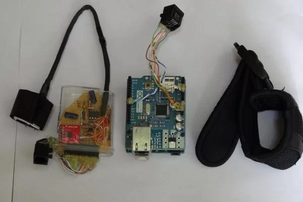
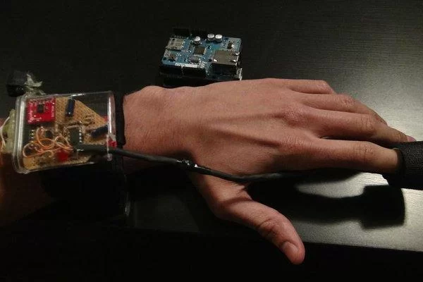
The Sleep n’ Tweet is basically just an Arduino with an Ethernet shield that keeps track of your vitals (movement + heart rate) as you sleep. I haven’t push it nearly as far as it could go, think of it more as a working prototype than a polished product – but the potential is huge! It could be used to track vitals at any time and tweet anything you want according to whatever filters you put on it. It could be manufactured to be very, very small. And it could also be stuck to just about anything to check for movement and IR or flow changes – but for now we’ll stick to sleep.
Step 2: How It Works
Overview
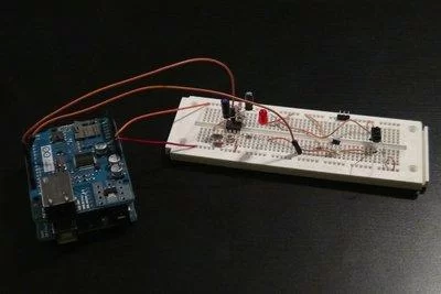
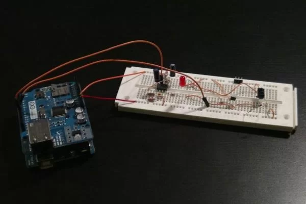
So here I’m going to give you a rundown of how the device works and functions so you at least understand what you’re about to make. If you’re just keen on having your own you can skip this section, I won’t be hurt if you do. I’m going to go all engineering lab report here. In 3…2….1….GO! So this device uses the Arduino for its base. The Arduino knows and does all once we program it. It doesn’t know a thing until we do that. On top of the base is the Arduino Ethernet shield which lets the Arduino talk to all the internets out there. Thus allowing the Arduino to communicate with Twitter with a little bit of programming. Steming from the Arduino are two sensor circuits; the accelerometer and the IR heart rate sensor. We’ll get to those in a minute though.
Arduino
For this project I used the Arduino Uno and an Ethernet shield on top of this. You need to make sure that pins 12 and 13 (point to pins in picture) are open because these will be used for communications between the Arduino and the Ethernet shield. Which sucks because pins 12 and 13 are my favourite to use. I don’t know what it is about them just like the numbers, but that took me 30 minutes to find out. So I used pin 9 to control whether or not the Infrared LED and red LED are active and I used pin 8 to read whether or not there was a change in the IR photo transistor. Pins A0, A1 and A2 were used to take care of the accelerometer. For power, I connected the 5v pin to the heart rate circuit and connected the 3.3v pin to the accelerometer circuit. That is basically how I hooked up the brains of the device. Still plenty of pins open for other things, maybe a moisture sensor to see if you’re sweating buckets in your sleep. Or a pressure sensor to see if you’re crushing a limb for hours and hours every night.
Heart Rate Sensor
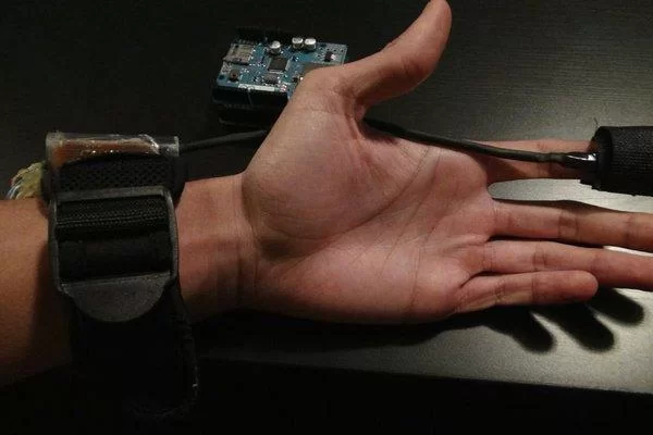
The heart rate sensor is comprised of an op amp connected to an IR LED and an IR photo transistor. In short, the design works by shinning an IR LED onto your finger and receiving some amount of light through the photo transistor. When your heart pumps blood, the volume of blood in your finger will change, and so will the amount of light picked up by the photo transistor. This value change will be pretty small so we’ll need to kick the change up a couple of notches with an op amp. The one I’ve set up should roughly multiply the signal by about 10 000 times. Now what we can do with this amplified signal is pump it into the Arduino and read the changes as ones and zeroes. I’ve also hooked up a LED between the Arduino and the op amp so you can directly view the signal going into the Arduino. What I’ve done is measured the time in between heart rates and after 5 beats, I take the average to compose a beats per minute. I also have filters in place in the program to rule out any unreasonable frequencies. For example, if the heart rate comes out to be 100ms between beats, I know this reading is false because the human heart cannot beat 600 times per minute. I made the valid range 30BPM to 250BPM. I found the IR sensor works on multiple parts of the body, but best on the finger.
Accelerometer
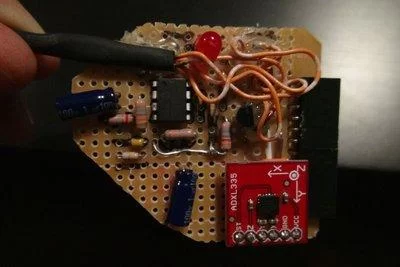
I used an accelerometer pre-assembled from Sparkfun called the ADXL335, but you can build your own which isn’t that hard.(The schematic is here ) The accelerometer is directly hooked up to the analog pins of the Arduino. Constant readings are given about it’s orientation and I basically I detect the changes in the orientation and log them as movements. I had to do a couple of things in the program to combat irregularities such as twitches. I take a time frame in which the number of movements read is compared to the number of non-movements read. Then, I also change the sensitivity. So if you move by 5 it will detect a positive movement. Basically, more movement equals a higher change in number.
Put it all together and you have a way of reading someones heart rates and movements. Lets move on to what you actually have to get to build this bad boy.
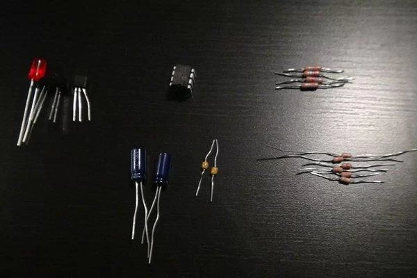
Step 3: Parts/Tools/Skills
Step 4: Schematics
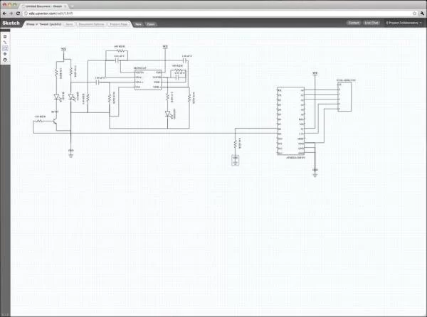
To make these I used the Upverter EDA tool – which is a pretty new and different, so I’m going to spend a minute explaining it. You should really just check it out at upverter.com, but for lack of a better analogy its Google Docs vs. Microsoft Word. There is a lot less feature bloat, it runs in your web-browser, its collaborative, its open source hardware focused, and its the first tool ever that allows me to share my designs on the web without resorting to PDFs. I can actually take the designs I build in Upverter and embed them into other sites a’la YouTube – which is very, very cool. My friends can then play with my design, export a BOM, order the parts or even fork it and make their own changes, and then something cool is possible… What I’ve designed becomes a building block of future electronics rather than a dead end project in my basement. Now Upverter is far from finished, and there are a lot of features coming down the pipe, but its to the point where we have tons of users signing up, forking content, creating parts, and just generally designing cool electronics. You should really check it out, join up and help shape the future of electronics design. You can directly take a look at the schematic and edit it here:http://upverter.com/mkiss/1645/Sleep-n’-Tweet/.
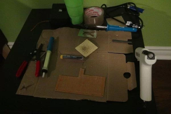
Step 5: The Build
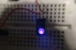
If you want to make sure your IR LED is working properly grab a camera. The human eye is incapable of detecting IR light, but it will show up on any camera as a bright whitish purple.
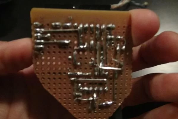
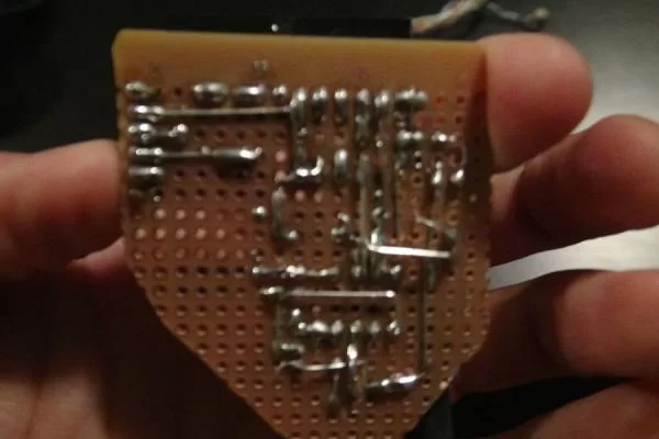
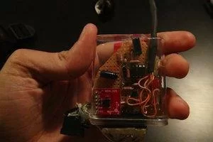
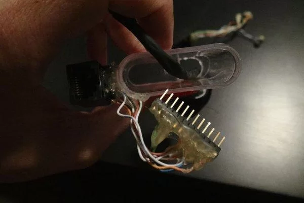
A couple of things I found were flattening the 1 uF capacitors really lowered the profile of the device so I could get it into the plastic case I found. Without doing this the device will jab you when you sleep. I used a hack saw to trim the PCB down to a reasonable size so I could fit everything in the case and used some nice wiring to extend the reach of the IR sensor.
I then soldered the components all together and that’s all there was to do. I hot glued the wires to the top of the PCB too so they wouldn’t break off. When I first had my boss sleep with it he mangled the wires and broke a few. So I lathered the hot glue on the connectors to Zak proof it. I was also fiddling around with the sensor when the wire snapped and it was a real pain to get it back on so I recommend gluing the top. Even though it doesn’t look the prettiest, it prevents a lot of pain, suffering and loss of time.
Step 6: Programming
Utility Functions
The only utility I have is taking the 5 beat read times and averaging them then converting them to a beats per minute.
Twitter
This is where the twitter message is processed and sent. You are alerted if something goes wrong and given the error message from twitter in the serial monitor. This is an important one because networks are always a pain. Also not twitter gets upset when you send duplicates. So when you’re heart is the same for two tweets in a row and you are or aren’t moving. It will not tweet unless something has changed.
Sensors
In the check movement function you can see that past and present values are compared to see if there has been a change. The change being a movement of some kind. I have if statements set up so movement is detected in all three dimensions and I have a sensitivity set up so you can change exactly how much movement sets off the movement function. The number of times moved is then compared to the total number of movement reads and then a final verdict is passed whether there was or was not movement during the time period. These time periods are like windows. So if I move in the 30 second window, the Arduino will tweet that I have moved within 30 seconds. If I’m still, it will say I remain still until the next window. It’s also been filtered so going to itch your nose or things like that won’t be counted as total movement.
The heart rate sensor counts the amount of time between each heart beat for 5 beats and then averages them. The time between beats will not be recorded if it is outside the range of a human heart. Otherwise every twitch or touch of the sensor would register as a wild beat per minute value. Unless you’re Lance Armstrong or a humming bird your BPM should be between 30 and 220. In studies done below 30BPM is extremely unlikely and over 250BPM usually means a doctor would like shock you with a defibrillator. This range can easily be changed in the program if you just so happen to be Mr. Armstrong. Or a humming bird squirrle man thing.
Output
This is where you will spend a lot of time if any mistakes are made. I spent a couple of hours blankly staring at this window for many hours during this project. I hope you do too, because if it works the first time you didn’t do it right.
The output simply takes all recorded information and outputs it to the serial console in the printStatus function. This is for any troubleshooting or inquiry.
The tweetStatus takes the information gathered from the sensors and tweets a message depending on what state you are in during your sleep.
Arduino Functions
Just the setup and the main loop. Pretty self explanatory.
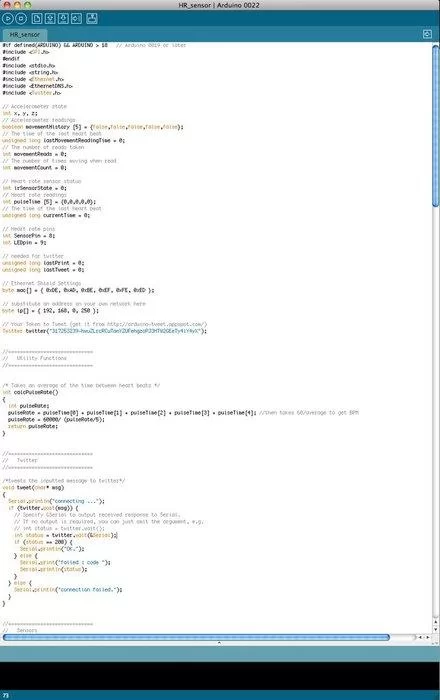
Here’s the Code:
#if defined(ARDUINO) && ARDUINO > 18 // Arduino 0019 or later
#include
#endif
#include
#include
#include
#include
#include
// Accelerometer state
int x, y, z;
// Accelerometer readings
boolean movementHistory [5] = {false,false,false,false,false};
// The time of the last heart beat
unsigned long lastMovementReadingTime = 0;
// The number of reads taken
int movementReads = 0;
// The number of times moving when read
int movementCount = 0;
// Heart rate sensor status
int irSensorState = 0;
// Heart rate readings
int pulseTime [5] = {0,0,0,0,0};
// The time of the last heart beat
unsigned long currentTime = 0;
// Heart rate pins
int SensorPin = 8;
int LEDpin = 9;
// needed for twitter
unsigned long lastPrint = 0;
unsigned long lastTweet = 0;
// Ethernet Shield Settings
byte mac[] = { 0xDE, 0xAD, 0xBE, 0xEF, 0xFE, 0xED };
// substitute an address on your own network here
byte ip[] = { 192, 168, 0, 250 };
// Your Token to Tweet (get it from http://arduino-tweet.appspot.com/)
Twitter twitter(“Put your token in here.”);
//=============================
// Utility Functions
//=============================
/* Takes an average of the time between heart beats */
int calcPulseRate()
{
int pulseRate;
pulseRate = pulseTime[0] + pulseTime[1] + pulseTime[2] + pulseTime[3] + pulseTime[4]; //then takes 60/average to get BPM
pulseRate = 60000/ (pulseRate/5);
return pulseRate;
}
//=============================
// Twitter
//=============================
/*tweets the inputted message to twitter*/
void tweet(char* msg)
{
Serial.println(“connecting …”);
if (twitter.post(msg)) {
// Specify &Serial to output received response to Serial.
// If no output is required, you can just omit the argument, e.g.
// int status = twitter.wait();
int status = twitter.wait(&Serial);
if (status == 200) {
Serial.println(“OK.”);
} else {
Serial.print(“failed : code “);
Serial.println(status);
}
} else {
Serial.println(“connection failed.”);
}
}
//=============================
// Sensors
//=============================
/* Checks if there has been a change in accelerometer position*/
boolean checkMovement() //function compares old values to new ones and detects only if a certain ammount of movement is happening
{
boolean ret = false;
int sensitivity = 3;
int newX, newY, newZ;
/* Read the new values */
newX = analogRead(0); // read analog input pin 0
newY = analogRead(1); // read analog input pin 1
newZ = analogRead(2); // read analog input pin 2
/* Check for changes */
if(x-newX > sensitivity || x-newX < -sensitivity)
{
ret = true;
}
else if(y-newY > sensitivity || y-newY < -sensitivity)
{
ret = true;
}
else if(z-newZ > sensitivity || z-newZ < -sensitivity)
{
ret = true;
}
if (millis() – lastMovementReadingTime > 30000)
{
for(int i = 4; i>0;i–)
{
movementHistory[i] = movementHistory[i-1]; //Updates the array so the first value can be changed
}
movementHistory[0] = false;
// Duty cycle = 10%
if (10 <= ((movementReads/movementCount)*100))
{
movementHistory[0] = true;
}
movementReads = 0;
movementCount = 0;
lastMovementReadingTime = millis();
}
if (ret)
{
movementCount++;
}
movementReads++;
// Store new values
x = newX;
y = newY;
z = newZ;
/* Serial.print(newX);
Serial.print(” “);
Serial.print(newY);
Serial.print(” “);
Serial.println(newZ);*/
// return whether there is movement
return movementHistory[0];
}
/* Reads the IR sensor and gets the time between heart beats */
int getHeartRate()
{
// Used to stor the status of the photo transistor
int newState = digitalRead(SensorPin);
// There has been a change
if(newState != irSensorState)
{
if(newState == 1)
{ //beat is 1 or 0 this if statment is only entered when a 1 turns to a 0 or a 0 to a 1
for(int i = 4; i>0;i–)
{
pulseTime[i] = pulseTime[i-1]; //Updates the array so the first value can be changed
}
/*
* This is the filter for the system. The heart-rate is not allowed to go above 250BPM or below 30BPM
* Other filtering methodes. Check if the value between beats is greater than a certain level. A big change doesn’t work, weighted mean. delay stuff.
*/
if(millis() – currentTime > 240 && millis() – currentTime < 2000 /*&& isMoving() == false*/)
{
pulseTime[0] = millis() – currentTime; //keeps the time between beats to a reasonable range to avoid confusion
}
}
if(newState == 0)
{
currentTime = millis();
}
// Store the new state
irSensorState = newState;
}
// calculates the pulse rate at the end
return calcPulseRate();
}
//=============================
// Output
//=============================
/* Prints all information to the serial monitor */
void printStatus(boolean isMoving, int pulseRate)
{
if (millis() – lastPrint >= 1000)
{
// Print movement status
Serial.print(“Movement: “);
if (isMoving)
{
Serial.println(“True”);
}
else
{
Serial.println(“False”);
}
// Print pulse status
if(pulseTime[4] == 0)
{
Serial.println(“Calibrating”); //if 5 readings have not been taken the device is still calibrating
} else
{
Serial.print(pulseTime[0]); //Prints the data
Serial.print(“, “);
Serial.print(pulseTime[1]);
Serial.print(“, “);
Serial.print(pulseTime[2]);
Serial.print(“, “);
Serial.print(pulseTime[3]);
Serial.print(“, “);
Serial.print(pulseTime[4]);
Serial.print(“, “);
Serial.print(“BPM: “);
Serial.println(pulseRate);
}
lastPrint = millis();
}
}
/* Finds the apprpriate message according to movements and pulse rate and sends the message to the tweet function */
void tweetStatus(boolean isMoving, int pulseRate)
{
char msg[140];
//Is the length of time between tweets and other filters to decide which message should be sent to twitter
if (millis() – lastTweet >= 300000) //5 minutes
{
if(pulseRate > 120 && isMoving)
{
sprintf(msg, “Awake with a pulse rate of: %d”, pulseRate);
}
else if(pulseRate > 120 && ! isMoving)
{
sprintf(msg, “Exciting dream with a pulse rate of: %d”, pulseRate);
}
else
{
sprintf(msg, “Sleeping with a pulse rate of: %d”, pulseRate);
}
tweet(msg);
//updates the last time since a tweet was made
lastTweet = millis();
}
}
//=============================
// Arduino Functions
//=============================
/* The Arduino setup function */
void setup()
{
delay(1000);
Ethernet.begin(mac, ip);
Serial.begin(9600);
pinMode(LEDpin,OUTPUT);
pinMode(SensorPin,INPUT);
digitalWrite(LEDpin,HIGH); //Controlls weather the IR LED is on or off
}
/* The Arduino run loop that checks the sensors and then sends a tweet depending on the status of the sensors*/
void loop()
{
boolean isMoving = false;
int heartRate = 0;
/* checks the accelerometer for changes too see if the device is moving or not*/
isMoving = checkMovement();
/* calculates the average heart rate in beats per minute according to differences detected by the IR tranistor*/
heartRate = getHeartRate();
/* sends a message to the serial console*/
printStatus(isMoving, heartRate);
/* sends a message to twitter depending on the users heart rate and movement*/
tweetStatus(isMoving, heartRate);
}
Step 7: Casing and Base

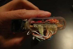
I started with just a header and connected the two using the bare wiring from the cable, but when I tested this the wires were broken and the connector was removed after sleeping with it. I remember waking up tangled in cables because the header got disconnected which made me panic and break more stuff before quickly before falling back to sleep. So I decided on just using the RJ45 connector which is nice and secure with lots of glue. After that I modified another female connector to fit on top of the Arduino so I could hook the two up together. Then I was done!
Step 8: Final Thoughts and V2.0 Ideas
About The Author
Hassan Zaka
I am an expert in accounting and possess diverse experience in technical writing. I have written for various industries on topics such as finance, business, and technology. My writing style is clear and simple, and I utilize infographics and diagrams to make my writing more engaging. I can be a valuable asset to any organization in need of technical writing services.
Follow Us:LinkedinTwitter