Overview of Project Coffee: Es(pi)resso Machine
A Raspberry Pi was integrated into a Gaggia Classic espresso machine to improve temperature stability and add features: PID boiler control via an SSR and PWM, digital temperature sensing (DS18B20 then TSIC306), pump control with SSR/IGBT for PWM pressure modulation, flow sensing for measured shots, ultrasonic water-level sensing, and an LCD touch display. Software uses PIGPIO and C++ threads; data logging and network access via Samba. Hardware and safety cautions are emphasized.
Quick Solutions to Questions related to Es(pi)resso Machine:
-
How is the boiler power switched and controlled?
A Solid State Relay replaces the coffee thermostat and is driven by Raspberry Pi hardware PWM (GPIO18) to provide proportional control using PID. -
Can the system measure and dispense a measured shot automatically?
Yes; a flow sensor is used to count pulses and the pump is switched by the Pi to dispense a measured shot, stopping automatically or when the button is pressed again. -
What temperature sensors were used and why was TSIC306 chosen?
Originally a DS18B20 was used; the TSIC306 was later chosen for higher range (up to 150°C), faster sampling (10Hz) and 0.1K resolution. -
How is water level measured without contacting the water?
An ultrasonic HC-SR04 range finder measures distance to the water surface, converting that to a water level estimate without contact. -
Does the Raspberry Pi log data and provide a display?
Yes; temperature, pressure, flow and time are logged to CSV files accessible over the network, and a HY28A/HY28B LCD shows status and readings.
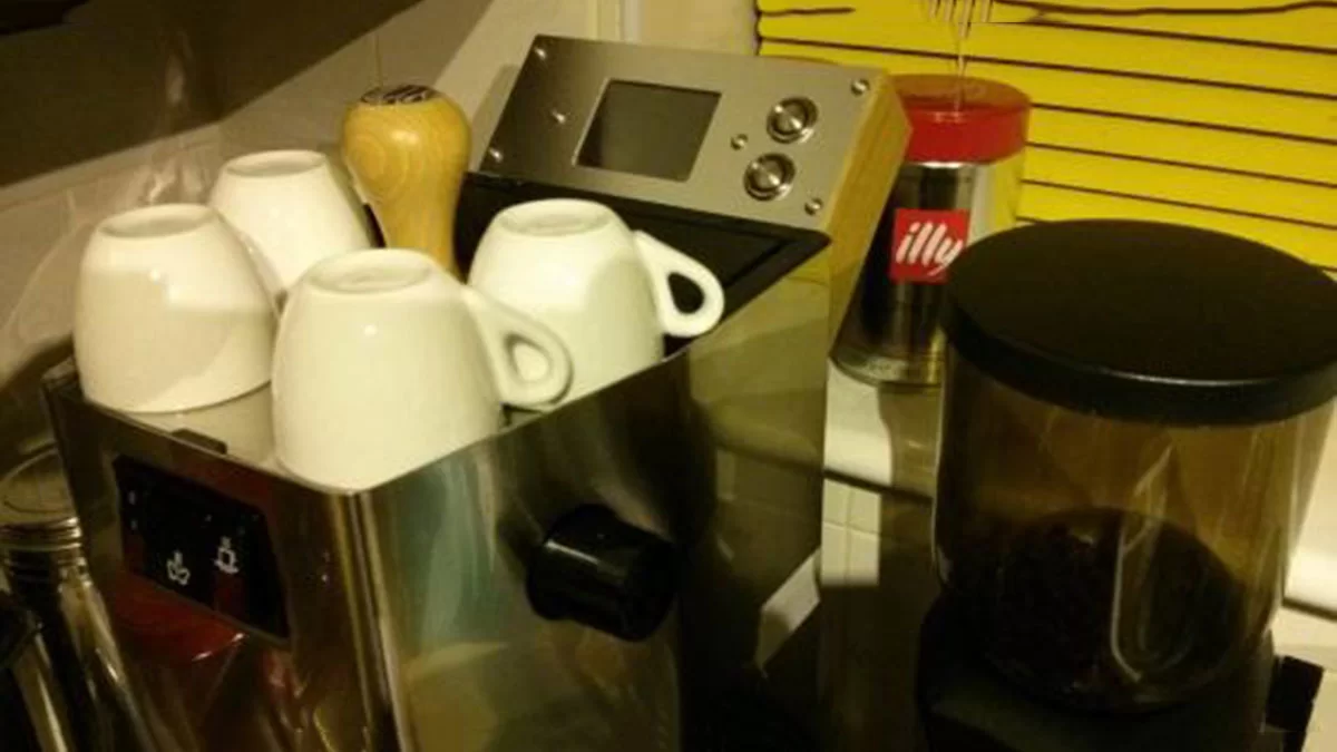
Some time ago, I embarked on a project to control my Gaggia Classic Espresso machine with a Raspberry Pi. Obviously, you can buy a fully automatic “bean to cup” machine… but where’s the fun in that!
This project started out with the simple idea of improving the temperature stability, and grew into a more elaborate controller with an LCD screen, water level sensing and pump control. This is an attempt to document the project (partly for my own notes), which I hope to update as I continue to tweak the design.
The project described here is for a Raspberry Pi, although some of the information could certainly be applied to other controllers. If you are interested in an Arduino project, take a look at this great project here also.
In this setup, the machine currently boots up automatically when powered on, regulates coffee temperature, displays current temperature, pressure and water level on an LCD and logs time, temperature, pressure and flow data to CSV files, which are accessible over the wireless network via Samba.
Currently, there are two push buttons on the front panel. The top one automatically dispenses a measured shot, using a flow sensor and automatically switching the pump on/off. This can be interrupted by pushing the button again. The lower button has two functions: a short push will toggle the boiler power off or on, whereas a long push will cause it to safely shut down the system.
The system has a “shot timer” showing elapsed time during a shot. In future there are lots of other possibilities such as showing the volume of coffee dispensed, temperature and pressure graphs, and an interface to adjust settings.
Other ideas not fully thought through include pre-infusion, pump modulation and possibly running the pump intermittently during steaming to top up the boiler. I’ve recently built some new hardware for pump pressure modulation and the next step is to implement the user interface to control that…
Obligatory Warning
Needless to say, this project involves using high voltage mains wiring at high current, as well as the high temperature and high pressure components inside the machine, and the combination of electrical components with water which can obviously be very hazardous. Please don’t attempt to copy any of the circuit diagrams or descriptions here unless you fully understand these risks, and are confident you know exactly what you are doing.
Boiler Control
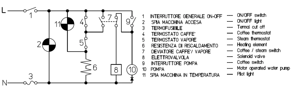
The boiler in the Gaggia Classic has two heating elements embedded in the sides of the boiler. These are normally controlled by a pair of thermostats – one for coffee temperature, and one for steam temperature. Again, these thermostats are wired in series with the element, and the steam button simply bypasses (effectively shorts out) the coffee thermostat. When the steam button is turned on, then only the steam thermostat can interrupt power to the boiler.
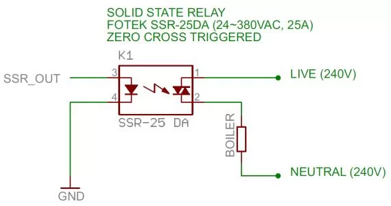
The circuit diagram below is for the original Gaggia Classic (the 240V model).
To control the boiler with a Raspberry Pi, we need to switch mains power at about 1300W. We will also want PWM (Pulse Width Modulation) to allow proportional control of boiler power. The best solution is to use a Solid State Relay (SSR), which allows us to efficiently switch power to the boiler. Unlike a mechanical relay, it switches very quickly (essential for PWM) and has no mechanical parts to wear out. Better still, we can select one with zero-cross switching (i.e. the SSR only switches when the mains voltage crosses zero, avoiding spikes), built in opto-isolation (important for safety) and compatibility with logic outputs on the Raspberry Pi.
The SSR will replace the coffee thermostat, so that the boiler can be proportionally controlled, based on temperature measurements taken by the Pi. The model used in this project is the Fotek SSR-25 DA(pictured below). It’s rated for 25A load and operating voltage of 24~380V AC.
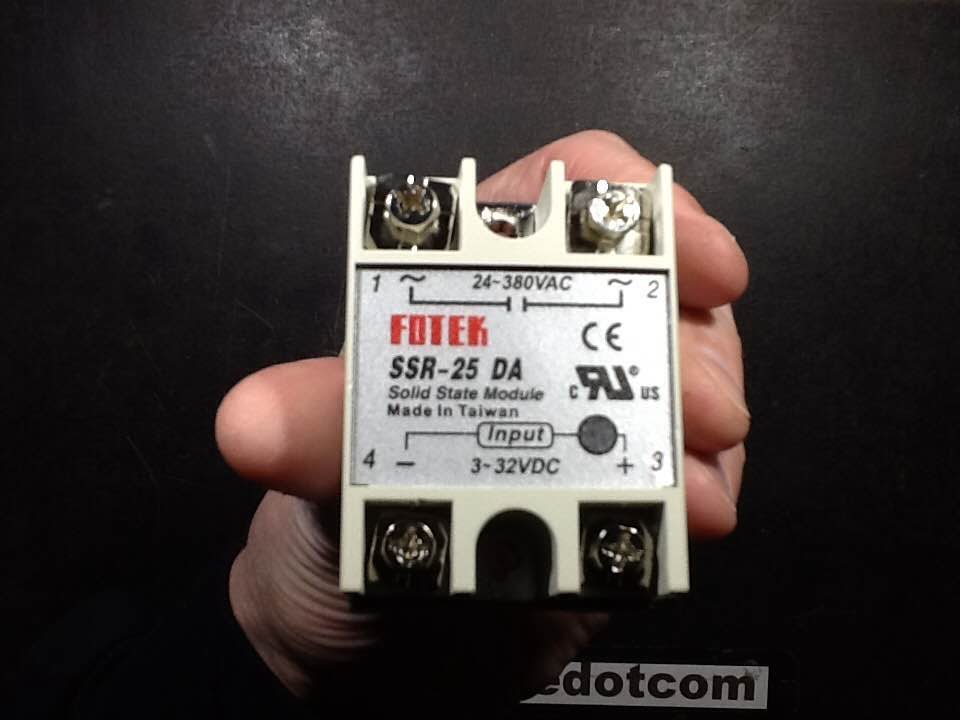
Caution: I’ve since read that and may not meet the rated current. Take care in selecting a suitable SSR for your mains voltage and load current.
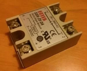
The SSR is screwed directly to the stainless steel body of the Gaggia, to provide a heat-sink. The mains cables need to be cable tied into the main loom, to keep them well away from the high temperature components. Note that insulating covers are available for the SSR terminals (not pictured below). The only place the SSR will really fit is at the back left hand side of the unit, near the pump (the water filler spout occupies a lot of space on the right hand side).
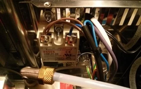
The Raspberry Pi has one hardware PWM pin (GPIO18), which we will use to control the SSR. The SSR-25 DA can be directly driven from a 3-32V input, and therefore works with the 3.3V logic level GPIO pin on the Pi. The negative input terminal of the SSR is connected to GND, and the positive input to the GPIO pin. The SSR even has an indicator LED to show when it’s triggered.
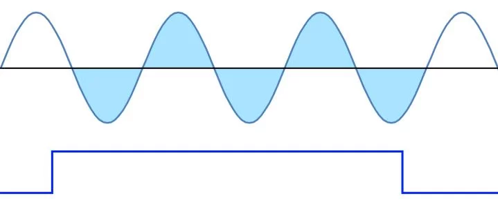
Since the SSR will only switch where the AC signal crosses zero, this means we need to use a fairly long PWM cycle time (low frequency) in order to get any kind of useful control of the boiler. With 50Hz AC, we have 50 cycles of the mains per second, and 100 points where it crosses zero. Effectively, the boiler can be turned on for whole units of 10ms. Therefore, if we have a 1 second PWM cycle time, we would be able to vary the duty cycle with about 100 discrete levels, or 1% steps.
However, the lowest rate for the Raspberry Pi hardware PWM seems to be about 1.14Hz (with PWM clock of 4095 and range of 4096). Thinking it would be better to use a sensible multiple of the mains frequency, I’m using a clock divisor of 2400 and range of 4000 for a PWM frequency of 2Hz. This means we have 50 “half waves” for each PWM cycle, which means we get a lower resolution of 50 discrete levels (still pretty good).
To control the boiler I use a PID (Proportional Integral Derivative) control loop. At each time-step, this takes a current temperature measurement and, based on the desired target temperature and PID control parameters, calculates the boiler output (the duty cycle for the PWM).
The control parameters of the PID are then tuned to give the best performance.
The pilot light (neon) on the front panel will still flash on and off as the SSR switches the boiler, so we can see when the boiler is operating. The light will be off whenever the boiler is on. As it reaches the target temperature, it will be on almost constantly.
Digital Thermometer
To measure the temperature of the boiler, there are many different options available. We could use a thermocouple or a temperature sensor with linear output, but this would require ADC and, potentially, needs calibration.
In this project, I originally used the Dallas DS18B20 Digital Thermometer, which has a number of advantages. First, it is already calibrated and accurate to +/-0.5°C. It also uses a serial digital interface that can be easily interfaced. Finally, it uses a 1-wire bus interface that means we can potentially add several temperature sensors to a single bus. This reduces the amount of wiring needed and, more importantly, the number of GPIO pins needed.
Naturally, there are some disadvantages also. The sensor has an operating range from -55°C to +125°C, and we could potentially exceed +125°C in steam mode. Also, it has a fairly slow conversion rate which can be as high as 750ms with 12-bit resolution.
Originally, I spread the DS18B20 with thermal paste and cable tied it flush to the aluminium body of the boiler, in the vicinity of the existing thermostat. This performed well, and I ran the machine like this for several months.
When I first interfaced the sensor to the Gaggia, I wrote my own code in C++ to talk to the DS18B20, and set the resolution to 10-bit, which gave a reasonable conversion time of 187.5ms and resolution of 0.25°C. I later found that there was an existing kernel module called w1-therm which directly supported the DS18B20, and decided it would be preferable to use this instead. The major disadvantage of the w1-therm module is that it hard-codes the resolution to 12-bit, with a very slow 750ms conversion rate.
Temperature Sensor Upgrade: the TSIC306
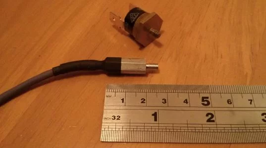
Eventually I upgraded to the TSIC 306 sensor which offers a higher temperature range and faster update rate compared to the DS18B20.
Like the DS18B20, the TSIC 306 is a factory calibrated digital temperature sensor which communicates over a simple 1-wire bus. It has an accuracy of +/-0.3K, resolution of 0.1K, measurement range from -50°C to +150°C and sampling rate of 10Hz. It is available in a TO92 package with three wires (VCC, GND and DATA) and can be directly interfaced to a single GPIO pin.
Of course nothing is perfect and one disadvantage of the TSIC 306 is that it requires a separate GPIO for each sensor (where you could have 100 separate DS 18B20 on a single wire bus!) However, for this application, I can live with that limitation.
The new temperature range of 150°C is much more suitable, given the high boiler temperatures that we could reach during steaming.
I’ve encapsulated the sensor in a hex spacer (more details), and insulated with heat-shrink as pictured below (bottom) next to the original thermostat (top). This screws straight into the side of the boiler, replacing the existing thermostat.
Reading the sensor from user mode worked but was a little unreliable due to unpredictable OS interruptions. To improve reliability, I wrote a kernel driver to talk to the sensor, which I used for about 8 months. Later still, I re-implemented it again using the PIGPIO library, which is the current version used. The new sensor is now installed and running on the machine, and seems to perform very well.
Pump Control
The pump in the Gaggia Classic is an Ulka EP5 vibratory pump, which develops 15bar pressure and is rated at 48W. It has an integrated diode, and is powered directly by 240V mains.
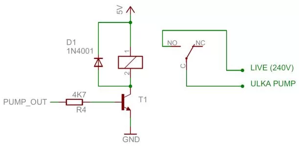
To switch the pump on and off with the Pi, I initially used a relay. This was switched from the Pi with an NPN transistor, resistor and diode across the relay coil. The normally open contacts of the relay were wired in parallel with the existing manual pump switch, so that manual control was still possible. Therefore, the pump could be turned on/off manually, and on/off from software by the Pi.
This has now been replaced (as will be described shortly), but here are the details for the record: the relay was a Rayex Elec. LEG-6 cube relay (coil resistance 100 ohms, nominal coil voltage 6V and current 60mA). The contacts were rated for 10A resistive load and 5A inductive load at 240VAC. The transistor was a 2N4401 NPN. This was the circuit originally used:
More recently, I replaced the pump controller circuit with an upgraded design using an SSR to switch the pump power on/off, and an IGBT to allow the pump pressure to be modulated using PWM. This is documented separately on these posts (which describe development from first prototype to custom PCB manufacture):
Ulka EP5 Pump PWM Pressure Modulation
High voltage output stage circuit diagram
PCB Design for the IGBT Driver Board
The design still allows for the pump to be switched manually using the front panel switch, but it can also be switched in software using an SSR. When the pump is on, an IGBT can be used to chop the supply rapidly (1kHz – 2kHz) to regulate pressure.
Analogue Pressure Sensor
To measure pressure, I’ve added a Danfoss AKS32R analogue pressure sensor with 0-300psi range (20.68 bar).
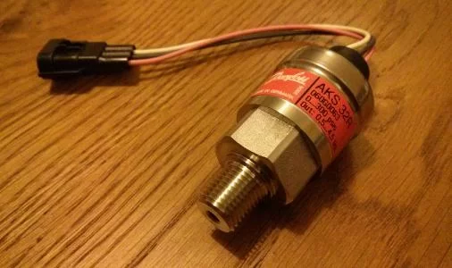
There are more details on the sensor in this post. Since the Pi doesn’t have any analogue inputs, I’m using the Adafruit ADS1015 board to interface this to the Pi.
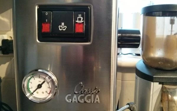
I’ve also installed a front panel pressure gauge (manometer) which is useful for calibration It also looks really cool on the machine 🙂
To connect the pressure sensor and gauge, I cut the high pressure output hose from the pump and inserted a push-fit T piece. Then I ran some 6mm PTFE tubing from the new output to another T piece, which is connected to both the pressure sensor and front panel gauge.
Logic Wiring
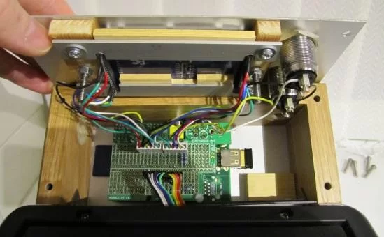
The logic level inputs and outputs from the Pi enter the machine on the ribbon cable pictured below. The first version used an ABS box (Hammond 100 x 50 x 25mm) which acts as a junction box for all the other components (flow sensor, digital thermometer, SSR, ultrasonic ranger and the pump relay). The ABS box only just clears the conical water filler spout, which enters the water tank through the large black hole visible in the centre right. I made a short aluminium bracket to suspend the box about 45mm below the ventilation slots.
Since then, I’ve added another ribbon cable to carry more signals (required for the pump modulation control), and some screened cable for the pressure sensor analogue output. I also needed a larger ABS box to accommodate all the new components. Frankly, it’s getting very cramped inside the machine at this stage!
The internal edges of the casing have sharp edges, and have been taped to protect the ribbon cable.
This is an old photo, and doesn’t show the pressure sensor and new wiring. I’ll upload a new picture soon, but suffice to say it is becoming a challenge to fit everything inside the machine.
Flow Sensor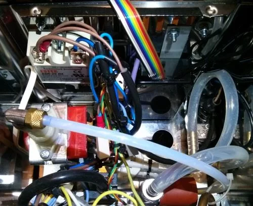
To dispense a shot, we need to be able to dispense a measured amount of water. Running the pump for a fixed length of time wouldn’t work, because the flow rate can vary depending on the quantity of coffee as well as the grind and tamp. We need a way to measure the volume of water that passes through the machine.
The obvious way to do this is to add a flow sensor. Since an espresso shot is a relatively small volume (30ml to 60ml), we need a sensor with fairly high resolution. We can’t put it on the output side of the pump because of the high pressure (~15 bar) and the vibratory pump could give erratic readings, and perhaps damage the sensor. We also don’t want it in contact with the boiler. Ideally, we also want something non-toxic and “food safe” since it will be plumbed into the machine!
When I first started looking, I could only find professional flow sensors ranging from £100 to £350 (!), and also some very cheap sensors which I was dubious about. After some searching, it occurred to me that I might be able to find a suitable spare part from an automatic machine (and this would have the advantage of being food safe). The sensor I ended up using was the Digmesa FHKSC 932-9521/B. This is a common spare part used on a wide range of machines (Krups, AEG, Siemens, Bosch, Nespresso, Jura etc.) It’s obviously ideal for this application and, as a spare, cost less than £10.
I didn’t think to take a photo before burying it deep inside my coffee machine, so here’s a drawing instead…
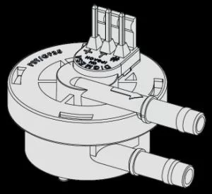
The data-sheet has full details of interfacing, performance etc. The sensor has a 7mm diameter nozzle with 1.2mm diameter bore, and generates 1925 pulses/litre. Of course this is a nominal value, and will vary in a real application (the manufacturer recommends calibration of the complete installation).
The sensor needs a minimum voltage of 3.8V, so it needs to be powered from the 5V rail. It has an open-collector output, but a pull-up to 3.3V doesn’t work, so I used the following level conversion to interface to the Pi:
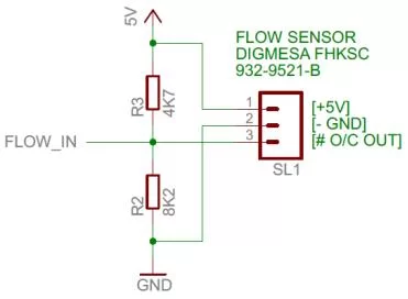
The maximum output voltage from the potential divider above should be 5V x 8.2 / (4.7 + 8.2) = 3.18V. The FLOW_IN signal above goes directly to a GPIO input on the Pi.
To measure the flow through the sensor, we simply need to monitor the input and count pulses. With a suitable calibration, these can be used to measure the volume of water dispensed.
The best place to locate the flow sensor is on the input side of the pump, so we can measure how much water is drawn from the water tank. The problem is that an OPV (Over Pressure Valve) lies between the output of the pump and the boiler. This valve regulates the 15bar pressure from the pump down to about 9-10bar, by opening at a set pressure. Normally, the output (waste water) from the OPV goes through some silicone tube back into the water tank.
This leads to a problem: if we measure the input to the pump, we can’t measure how much is lost through the OPV, so it won’t give us a true measure of how much water has been dispensed from the group head. To solve this problem, I simply added a T-connector to link the output of the OPV back to the input of the pump. This means that there will only be one tube hanging in the water tank, compared to the normal two.
The T-junction and flow sensor are just visible below (the flow sensor is the circular white unit in the centre right. The OPV is visible immediately above the flow sensor. The red rubber cover is where water enters the OPV from the pump, and the tube exiting the top of the OPV joins the T-piece which combines with the output of the flow sensor, and is connected to the pump inlet.
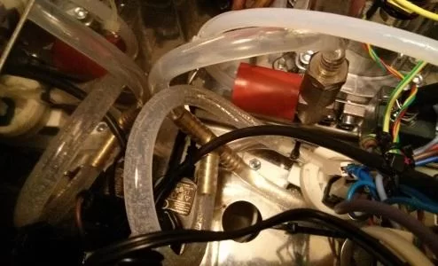
Note that the water filler spout enters the water tank through the large hole visible in the bottom centre of the image.
Measuring Water Level
To measure the water level in the tank we could use some kind of float sensor (e.g. with a potentiometer), or an optical system (e.g. optical distance sensor to a floating ball in a tube). However, these would both involve having material in direct contact with the drinking water, and could also be difficult to mount and clean. Instead, I decided to try using an ultrasonic range finder, which is non contact and will give a distance measurement that we can convert directly into an estimate of water level.
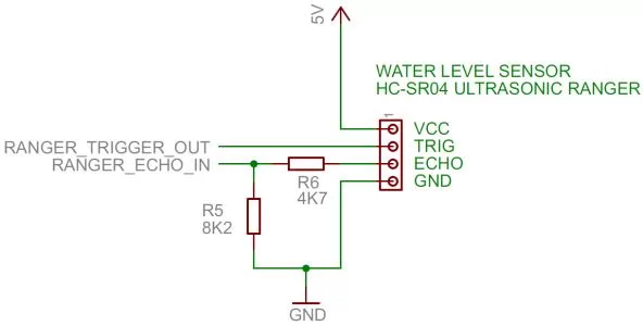
The HC-SRC04 (shown below) is very simple to interface, and provides a fairly accurate range measurement (claimed 3mm). It is also very low cost (typically less than £3).
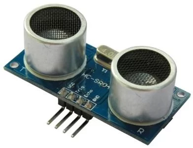
The module has connections for 5V power, GND as well as a TRIG input and ECHO output. To trigger the module, you give it a high pulse lasting at least 10us. It will then transmit 8 pulses of 40kHz ultrasound, and wait for the reflected echo. The ECHO pin will go high for a time period proportional to the distance. Using the speed of sound, we can calculate the distance.
The ranger is designed for 5V power and logic, so we need to use level conversion to interface to the 3.3V GPIO levels used by the Pi. In my case, I found that the 3.3V output from the Pi was sufficient to trigger the unit when directly connected to the TRIG input. However, level conversion is needed for the ECHO output as shown below.
To measure the distance accurately, we need to be able to time the ECHO duration quite precisely. Originally, I implemented this in C++ from user mode, using edge-triggered GPIO interrupts, and recorded a time-stamp at the start and end of pulse. Subtracting the two gives a measure of echo time.
However, due to unpredictable OS activity, the time measurements were not all that accurate, so it was necessary to use multiple sample averaging or filtering to obtain good results.
Eventually, I gave up on user mode and implemented a kernel driver which can achieve more accurate timing. This worked much more reliably (I would estimate about 2-3mm resolution), and gives a nice steady level indication on the LCD. More recently, I re-implemented the range finder with the PIGPIO library which makes the software much simpler to install and use.
Display
The display is the HY28A which is a 2.8″ Colour Touch Screen TFT LCD with an SPI interface for both the LCD and the touch sensor. It has since been replaced by a newer model HY28B.
This display has 320×240 resolution with 16-bit colour, and the SPI interface means that it only needs a small number of GPIO pins to interface. Amazingly, it cost under £10.
Some very slight negatives are that it uses 2mm pitch connectors instead of the more common 2.54mm (0.1″) and has no mounting holes.
When I bought this, I fully expected to have to write the code to drive it, but was surprised to find that Linux Framebuffer drivers are already available for this display, and many others.
I have this configured so that it displays a console on the LCD as soon the Pi boots, so that any boot messages can be seen. Rather than running under X Windows, I decided that the controller would run under the console to reduce overhead and use SDL to draw on the LCD.
Enclosure
The first version was installed in a standard Raspberry Pi case, and simply screwed to the outside of the case. I wanted a more permanent installation that would have space for a display, and something a bit neater looking.
Note that the factory protective film is still stuck to the LCD screen in these photographs, which is a bit dirty/scratched. I’m planning to buy some new screen protection material to replace it when I’ve finished tinkering with the hardware.
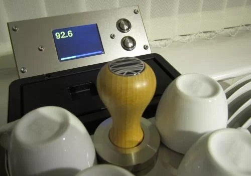
The current enclosure has two anodised, brushed aluminium panels (175 x 75 x 1.5mm), screwed to an oak frame. The frame is made from 50 x 15mm oak, with two glued mitre joints to make a frame 180mm wide and with two more 45 degree mitre cuts which mount flush to the rear of the machine. The frame is screwed to the machine through the ventilation slots, using two steel L-brackets with machine screws.
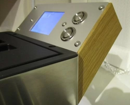
The front control panel is attached by four stainless steel M4 socket headed button screws. There are four holes drilled through the oak frame, and I used M4 inter screws (using only the female part of the original screw which appears to be BZP, and replaced the male screw with longer stainless steel button screws).
There’s a hidden plastic panel so that the electronics are completely enclosed, and to prevent hot humid air from the ventilation slots getting to the electronics. The existing ventilation slots are still open to the air at the rear of the machine.
The Raspberry Pi (Model A) is mounted directly to the rear plate, using a Pi support bar and two machine screws. There is very restricted space inside the unit, and I had to make a cutout in the frame to clear the (redundant) video phono connector. Also, the Pi is powered through the GPIO header, rather than the mini USB power connector.
The LCD touch-screen is (gently!) clamped to the front panel, for a flush fit.
Control Buttons
Although the display has a touch-screen, I decided that wasn’t ideal for daily use in the kitchen, so I’ve added two stainless steel buttons. In the first version, these used 4K7 pull up resistors to 3.3V and were active low, pulling the GPIO pin to ground when pushed. As I added more equipment to the machine, I began to run out of GPIO lines. The latest version uses a single analogue input with a resistor ladder to read all the buttons as described here.
Currently, one of the buttons is used to pour a shot, and one to turn off the boiler and halt the Pi so that it can shut down cleanly before the mains power is switched off. They can obviously be programmed in software for any function.
Complete Circuit Diagram
Here’s an (OUT OF DATE) circuit diagram for the old version. There were three 0.1″ (2.54mm) pin header connectors, P1 and P2 connected the Pi to the LCD touch-screen, and P3 connected the Pi to the machine (sensors and boiler/pump control).
This diagram is very out of date, because it’s missing the new wiring for the TSIC 306 which is currently wired on GPIO 24, analogue button matrix, pressure sensor, high voltage output side for controlling the pump etc. There are circuit diagrams for some of these elsewhere on the blog, and at some stage I will update this page properly.
Note that signals are named from the point of view of Pi, so for example RANGER_TRIGGER_OUT means an output signal from the Pi to trigger the ultrasonic range finder.
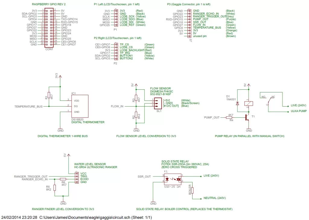
The P1, P2 and P3 headers are soldered to a Humble Pi board, along with the various pull-up resistors and potential dividers. All the wiring between the headers and the GPIO connector is underneath the Humble Pi board. The P3 connector is connected by a ribbon cable to an ABS junction box inside the main enclosure.
I’m using the Raspberry Pi model A because I don’t need the Ethernet and uses quite a bit less power. I’m using medium overclocking in Raspbian at the moment. With the Humble Pi mounted over the Pi and the enclosed space, I was a little concerned that it might overheat, but I’ve monitored the CPU temperature and it runs pretty cool so it seems this fear was unfounded.
Complete Source Code
The complete C++ source code for the project is available on Github here:
Espiresso Source Code (Github)
This is my own personal development version, so the code will obviously update as I make any changes to the software or hardware.
The software used to need kernel modules for the HC-SR04 and TSIC 306 sensors. However, these are no longer required since these libraries were rewritten to use the PIGPIO library, which makes it possible to obtain precision timing from user mode.
At time of writing, this software has been working well for over a year, and I’ve gradually added features and improved it to suit my own needs.
The temperature regulator runs on a separate thread, as does the display controller. Most of the sensors (such as the flow sensor and ranger) also use threads. In places, the code makes use of edge triggered interrupts (for the flow sensor pulse counting, range finding etc), to avoid busy waiting.
As far as possible, the majority of GPIO is now using the PIGPIO library, except for the hardware PWM used to regulate boiler power, which goes direct to the registers (in order to achieve a very low PWM frequency). Earlier versions used the sysfs GPIO interface, as can be seen in older revisions.
Performance of PID versus Thermostat
This graph is a comparison of the performance of the stock thermostat (blue) against the PID controller (red). The original thermostat oscillates wildly, compared to the more stable temperature control achieved with the PID. The small dip in the PID curve at around 780 is the temperature drop when pulling a shot.
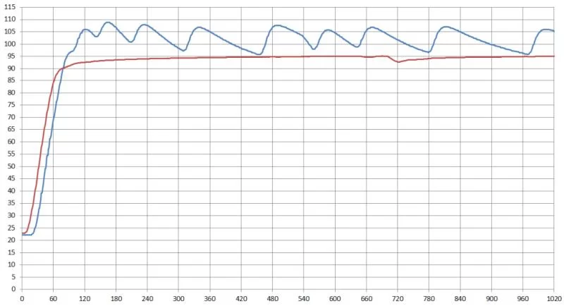
In the graph above, the PID target temperature was set to 95C. Since then, I’ve changed the set point to 93C and tuned the PID parameters to optimise the performance further.
Undocumented Things
This site is a work in progress, and I hope to update the content in future to add more explanation of how it all works. In the mean-time, feel free to ask questions in the comments!
Source: Project Coffee: Es(pi)resso Machine
About The Author
Hassan Zaka
I am an expert in accounting and possess diverse experience in technical writing. I have written for various industries on topics such as finance, business, and technology. My writing style is clear and simple, and I utilize infographics and diagrams to make my writing more engaging. I can be a valuable asset to any organization in need of technical writing services.
Follow Us:LinkedinTwitter


