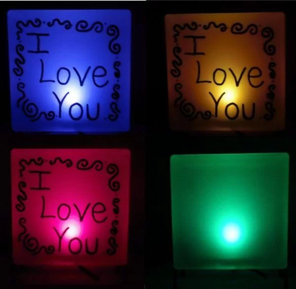
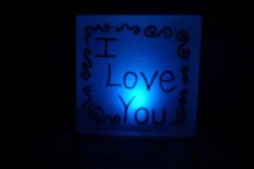
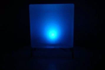
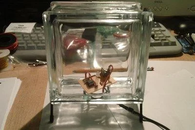
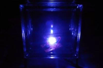
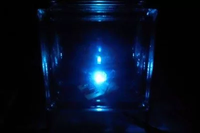
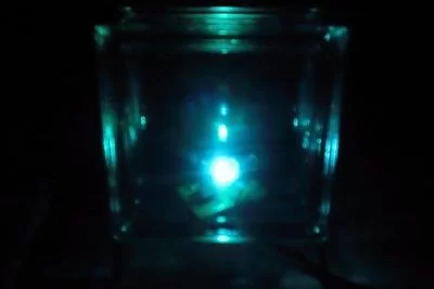
I wanted to create something for my wife as a present and this is what I came up with. This is a dark activated color changing night light. It has a sensor that can tell when the room light is turned off. This then will light a RGB LED and slowly fade through different colors. Its brains is a ATtiny85, but you could also use an Arduino. We have little boys that would appreciate this on at night.


Step 1: Parts
Parts for the Circuit:
- 22uf capacitor
- 10nf “103” capacitor
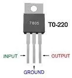
- 7805 voltage regulator
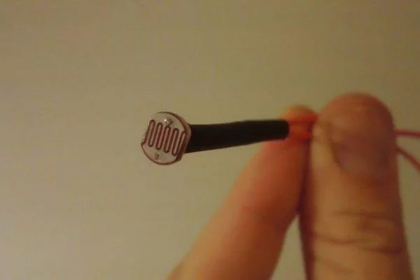
- LDR (Light Dependent Resistor)
- 2 – 10K resistor
- 2 – 100ohm resistor
- 220ohm resistor
- RGBLED(TheoneIgotfromRadioShackhasacommonanode.)
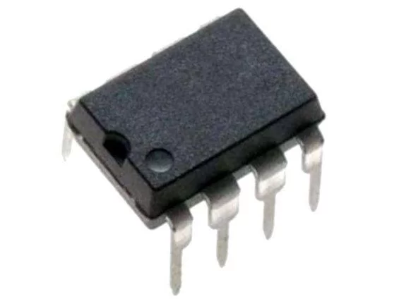
- ATtiny85 (can be bought at www.sparkfun.com)
- 8 pin socket
- Wire
- Perfboard
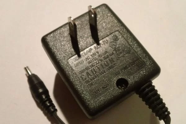
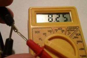
- WallWortPlug about 7-18V (test this with a voltmeter, don’t trust the label)
Everything can bought at RadioShack but the ATtiny85.
Don’t buy the Wall Wort Plug. You or someone you know probably has one they don’t use, like the plug to charge a cell phone… When possible, recycle.
Parts for the Light:
- Hobby Glass Block
- Hot Glue Gun
- Glass Block Stand
- Glass Frosting Spray Paint
- Paint Pen/Sharpie
Other Items:
- Computer
- Arduino
- Breadboard
- Jumper Wire
- Wire Stripper
- Voltmeter
- Soldering Iron
- Solder
- Razer Blade
Assumptions:
- That you at least have a little experience programing an Arduino and know how to solder on a perfboard. If you are an absolute beginner you may need some help.
Step 2: Programing
There are many great sites and other instructables that give step by step instructions on how to program a ATtiny85 with a Arduino.You could just use the Arduino instead of the ATtiny85 if you like. You would just have to change the pin locations in the code.
The reason I used the ATtiny85 was because it is a cheap chip and I wanted the smaller form factor. The ATtiny85 can be programed on a shield if you have one or right on a breadboard.
Check out:
- https://www.instructables.com/id/Program-an-ATtiny-with-Arduino/
- https://www.instructables.com/id/8-Pin-Programming-Shield/
Here is the sketch/program:
// attiny85 RGB LED rainbow fade with LDR
//By Matt Jenkins
const int redPin = 2;
const int grnPin = 4;
const int bluPin = 1;
int sensorPin = 3; // select the input pin for the ldr
unsigned int sensorValue = 0; // variable to store the value coming from the ldr
void setup()
{
pinMode(redPin,OUTPUT);
pinMode(grnPin,OUTPUT);
pinMode(bluPin,OUTPUT);
//Start Serial port
//Serial.begin(9600);//uncommentforSerialport//startserialforoutput–fortesting
}
void loop()
{
//readthevaluefromtheldr:
sensorValue=analogRead(sensorPin);
if(sensorValue>400){//settheLEDOFF//lowernumberforonwhendarkerorraisenumberforonwhenbrighter
digitalWrite(redPin,HIGH);
digitalWrite(grnPin,HIGH);
digitalWrite(bluPin,HIGH);
}
else{//FadethroughColors
redtoyellow();
yellowtogreen();
greentocyan();
cyantoblue();
bluetomajenta();
majenatored();
}
delay(30);
//ForDEBUGGING–Printoutourdata,uncommentthelinesbelow
//Serial.print(sensorValue,DEC);//printthevalue(0to1024)
//Serial.println(“”);
//delay(500);
}
void redtoyellow()
{
digitalWrite(redPin,HIGH);
digitalWrite(bluPin,LOW);
//fadeupgreen
for(bytei=1;i<100;i++){
byteon=i;
byteoff=100-on;
for(bytea=0;a<100;a++){
digitalWrite(grnPin,HIGH);
delayMicroseconds(on);
digitalWrite(grnPin,LOW);
delayMicroseconds(off);
}
}
}
void yellowtogreen()
{
digitalWrite(grnPin,HIGH);
digitalWrite(bluPin,LOW);
//fadedownred
for(bytei=1;i<100;i++){
byteon=100-i;
byteoff=i;
for(bytea=0;a<100;a++){
digitalWrite(redPin,HIGH);
delayMicroseconds(on);
digitalWrite(redPin,LOW);
delayMicroseconds(off);
}
}
}
void greentocyan()
{
digitalWrite(grnPin,HIGH);
digitalWrite(redPin,LOW);
//fadeupblue
for(bytei=1;i<100;i++){
byteon=i;
byteoff=100-on;
for(bytea=0;a<100;a++){
digitalWrite(bluPin,HIGH);
delayMicroseconds(on);
digitalWrite(bluPin,LOW);
delayMicroseconds(off);
}
}
}
void cyantoblue()
{
digitalWrite(bluPin,HIGH);
digitalWrite(redPin,LOW);
//fadedowngreen
for(bytei=1;i<100;i++){
byteon=100-i;
byteoff=i;
for(bytea=0;a<100;a++){
digitalWrite(grnPin,HIGH);
delayMicroseconds(on);
digitalWrite(grnPin,LOW);
delayMicroseconds(off);
}
}
}
void bluetomajenta()
{
digitalWrite(bluPin,HIGH);
digitalWrite(grnPin,LOW);
//fadeupred
for(bytei=1;i<100;i++){
byteon=i;
byteoff=100-on;
for(bytea=0;a<100;a++){
digitalWrite(redPin,HIGH);
delayMicroseconds(on);
digitalWrite(redPin,LOW);
delayMicroseconds(off);
}
}
}
void majenatored()
{
digitalWrite(redPin,HIGH);
digitalWrite(grnPin,LOW);
//fadedownblue
for(bytei=1;i<100;i++){
byteon=100-i;
byteoff=i;
for(bytea=0;a<100;a++){
digitalWrite(bluPin,HIGH);
delayMicroseconds(on);
digitalWrite(bluPin,LOW);
delayMicroseconds(off);
}
}
}
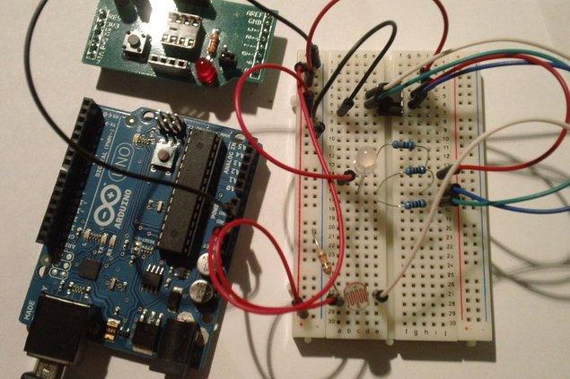
Step 3: Breadboard and Test
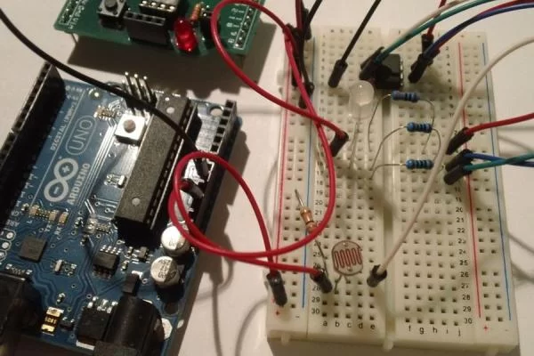
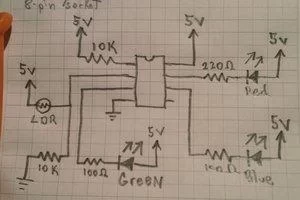
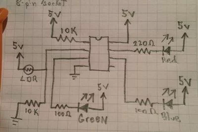
Now that your ATtiny85 is programed, I will describe how to make this circuit on a breadboard. You can view the pictures for clarification.
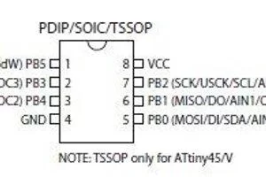
- You will notice that there is a small notch in one end on the top of the ATtiny85. The notch indicates the front. I will refer to the pins by number. And they are numbered like so. To the left of the notch is pin 1, and down the chip 2, 3, 4. Accost the chip and up back toward the notch is 5, 6, 7, 8. (see pic)
- You can use jumper wire to connect all the parts.
- You are going to use the Arduino to power the breadboard along the sides so you will have a row to 5v and row of ground, but don’t do it yet.
- Pin 1 is the reset and connects to ether side of the 10K resistor then the resistor goes to 5v. (doing this is called a pull-up resistor)
- Pin 2 receives the single from the sensor (LDR). So pin 2 connects to 2 parts. The LDR connects from 5v to Pin 2 and the other 10K resistor connects from ground to pin 2.
- Pin 3 connects to a 100ohm resistor, then through that goes to the Green LED pin. (or the negative side of a Green LED if using 3 different LEDs.)
- Pin 4 is the ground pin so just connect it to ground.
- Pin 5 is not used so it doesn’t get connected to anything.
- Pin 6 is connected to a 100ohm resistor, then through that goes to the Blue LED pin. (or the negative side of a Blue LED if using 3 different LEDs.)
- Pin 7 is connected to a 220 resistor, then through that goes to the Red LED pin. (or the negative side of a Red LED if using 3 different LEDs.)
- Pin 8 is the power pin and connects to 5v.
- Now connect the positive pin from the RGB LED to 5v. Since this is a common anode RGB LED there is one positive pin for all 3 colors. if you are using 3 seprete LEDs just simply connect those 3 positive pins (anodes) to 5v.
- POWER: Use the Arduino as the power source and connect the 5v to the breadboard positive power line and the Arduino ground to the breadboard ground lone.
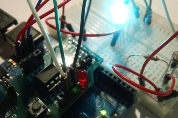
- It might flicker a bit when it is powered, but if the lights are on the LED should not light. So turn off the room lights to see if the LED turns on and starts fading through the colors. Then turn on the room lights again. Once the color cycle is done it will turn off.
- You can change for senitive you want the LDR sensor by reprograming it. Change the number 400 in the code to a higher number, around 700 to make it light up in a brighter lit room. Or lower the number to around 100 to make it turn on only when it’s really dark.
Step 4: Wall Plug Test

Now lets test it with the Wall Wort Plug.
- If you are like me then you have a bunch of these laying around from old phones and answering machines. Hopefully you have one you are not using and don’t need. The voltage is printed of the plug but you can’t trust it. The one i used said it was 3.7v but whe I tested it, it was 8.25v, over twice its printed value. So you need to find one that is between around 8 volts to around 18 volts. This will be dropped to 5 volts and the rest of the voltage will be turned to heat so if you have a higher voltage you may need a heatsink or it wlll get to hot.
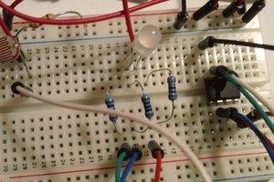
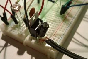
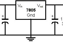
- To drop the voltage to 5v you need 3 parts a 22uf capacitor, a “103” 10nf Capacitor, and a 7805 voltage regulator. You can make this in the breadboard.
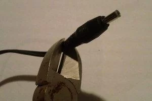
- First if you don’t have a matching female plug to use, just cut off the plug on the end of the cord and strip the wire about 1cm. Use your voltmeter to see which wire is positive and negative. (mixing them up will break your project)
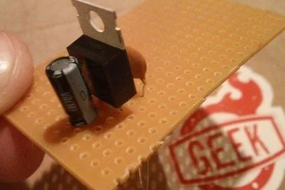
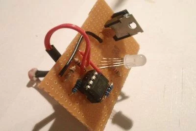
- The 22uf cap is polarized meaning it can only be installed one direction. The side with the white strip is the negative side and is connected to the middle pin if the 7805. Facing the front of the 7805, the left pin is the input and the other 22uf pin connect to that. On the back of the 7805 the 10nf cap connects between the 7805 middle and left (output) pins. (see pic) Your plug wire will connect to the 22uf cap. Make sure negative goes to negative and positive to positive.
- Unplug the jumper wires from the Arduino and plug them into the output and ground from the 7805. Plug it in the wall and it should work.
Step 5: On to the Perfboard
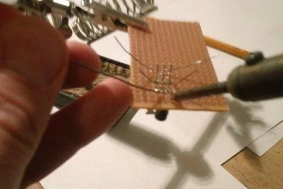
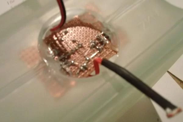
Breadboards are great for testing and prototyping but we need a smaller form factor and something more permanent so lets now make the circuit on a perfboard.
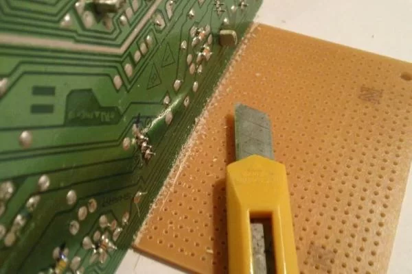
- You need to make sure that the board you will use is big enough for the project but small enough to fit in the glass block. You can measure it and score it with a razer blade along a strait edge. Then carefully snap it off along a table edge.
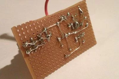
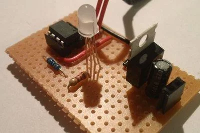
- You may want to start with the power. I used female headers to attach the cord but you can just as easy solder them right to the board. Once you installed the 22uf cap, 7805, and the 10nf cap you will have a place to attach the 5v and ground. Again, make sure you use the correct pins on the 22uf cap and the 7805. It is easy to mix them up.
- I placed the LED near the middle of the board so when it’s in the block the light will be in the middle. i also left the wires on the LED long. I thought it may look better once in the block. You can view finished pictures and be the judge if you want to do that.
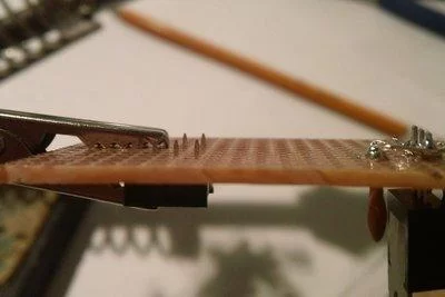
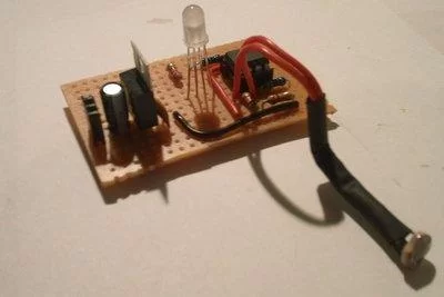
- I debated what to do with the LDR. I was going to glue it to the inside top of the glass block and leave a spot not frosted for it, but i didn’t think I would like the look. So I made this “probe” (see pic) to stick out the bottom just a bit. You can bend it to make it “just right.”
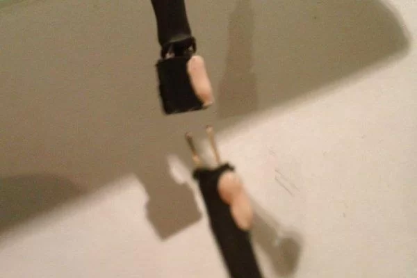
- I made a small plug for the cord so it can be taken off easily and if my child were to pull on the cord it would just come apart and not go flying. (see pic) This is not necessary though. If you do make this, you want to mark it with paint so you know what way it attaches.
When it is done you can test it in the block to see how it looks.
Step 6: Paint
You can do this one of two ways.
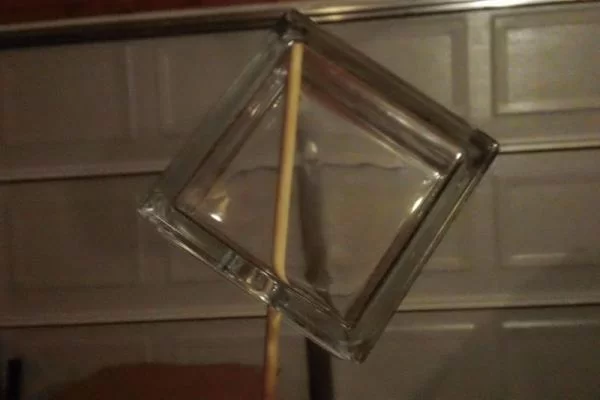
1. Put a wooden dowel in the block and spray it on all the sides with the Frosted Glass Spray Paint and find a way to leave it sticking up to dry. OR
2. Spray one side, let it dry, flip and spray that side, let it dry, flip…
Learn from my mistakes:
Do it slowly and don’t rush. I tried to hurry and put to much paint on and it started to drip. So I wiped it off which made it look worse. It took a few coats of paint to cover it up.
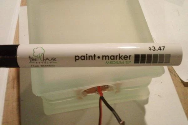
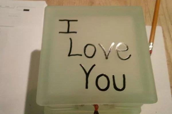
Message or Drawing?
Once it is dry you can use a paint pen or sharpie to write on the frosted surface. You may want to practice on paper of the same size first. I wrote on one side only. I should of had someone more artistic draw on mine, since I didn’t really like the look of my drawing, but there is the other blank side which looks nice.
Step 7: Finish It Up

Almost Done!!!
Take your little circuit board and apply some hot glue on the corners. Then moving quickly place it in the glass block. Make sure it is centered and gently pull it back till the glue cools. Then apply more hot glue around it along the edges just to make sure it is not going anywhere. Hot glue does not conduct electricity so it is OK if you glue over the wires.
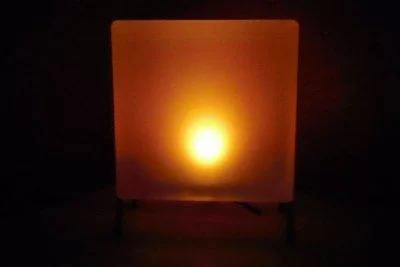
Set it in it’s stand, adjust the sensor, plug it in, shut off the room lights and enjoy your creation.
Step 8: Troubleshooting/Questions/More Info

If you can’t seem to get it to work, it could be one of these things…
- There is a short. Check over everything to make sure there are no wires or solder touching something that it should not be touching.
- Wrong polarity. This could be that the plug, LED, ATtiny85, 22uf cap, or the 7805 are in backwards.
- You may have burnt it out. If you put in the wrong resistors or wired the power wrong, it could have burnt the LED or the ATtiny.
- It’s just connect wrong. Go over the diagram and pictures carefully and make sure you have everything where it should be.
What is a LDR?
- LDR stands for Light Dependent Resistor. It resists the flow of electricity depending on how much light is shined on it. The more light the more it allows electricity to pass through. The darker it is by the sensor, the less electricity is passed through. The ATtiny85 measures just how much it “sees.”
What is a LED?
- LED stands for Light Emitting Diode. It is a diode meaning it only allows electricity to pass through in one direction. There are normally 2 ways to tell the positive and negative side of a LED. The positive side has a longer lead/wire and the negative side has a small flat notch on the edge on the lens, It also glows one wavelength of light. The different color LEDs have different elements in them that make them glow their color. It is not the color of the lens that colors the light. This is why you can have clear lens LEDs.
What is a RGB LED?
- It is one LED package with 3 LED’s in it. Red, Greed, and Blue. By fading through these 3 colors you can get about any other color. If all 3 are on at once you will get white light. The one I used from RadioShack had 4 leads from it. One positive (anode) lead and a one negative for each color.
Do you want more Geeks Videos or want ideas for projects?
- Check out my YouTube Channel at www.youtube.com/user/GeekGuyMJ
Questions?
- How to Solder? visit http://www.sparkfun.com/tutorials/106
- You can feel free to leave me questions or comments in the comment section below and I will do my best to get back to you and answer them.
If you like this Instructable please rate and vote for me in the contest at the top of the page. Thank You.
About The Author
Hassan Zaka
I am an expert in accounting and possess diverse experience in technical writing. I have written for various industries on topics such as finance, business, and technology. My writing style is clear and simple, and I utilize infographics and diagrams to make my writing more engaging. I can be a valuable asset to any organization in need of technical writing services.
Follow Us:LinkedinTwitter