Overview of Home Automation Lighting Control Systems
The article compares top UK home automation lighting control systems—Rako, Lutron, Fibaro, Futronix, and Control4—covering wired/wireless options, integration with phones/tablets and voice assistants, typical components (dimmers, keypads, hubs), compatibility (Z-Wave, Apple HomeKit), installation notes for old homes, and estimated prices for select modules. It advises choosing durable systems over low-cost alternatives and checking for neutral wiring before installation.
-
What systems support both wired and wireless installations?
Rako and Control4 offer both wired and wireless options; Lutron and Futronix focus on wireless and wired respectively. -
Can I control these lighting systems from my phone or tablet?
Yes; Rako, Lutron, Fibaro, Futronix (with extras), and Control4 support phone or tablet control via their interfaces or hubs. -
Do I need a neutral wire for smart lighting installations?
Yes; the article cautions that all smart lighting control systems require a neutral wire and advises confirming its presence before installing. -
Which systems integrate with voice assistants like Alexa or Siri?
Control4 and Fibaro can work with Alexa; Fibaro can integrate with Google Home and Apple HomeKit; Futronix can integrate with Amazon Alexa. -
What is recommended for older homes with existing wiring?
Rako (which can use old wires) and Futronix (designed for old homes with prewired compact panels) are recommended for older installations.
To get the right product is a bit problem for most of the customer when he/she searching for their own requirement, home automation lighting control systems available in many brands and style, it starts from a single room to a whole house system.
Here is the best home automation lighting control systems which starts from single room to a whole house
Rako lighting control system
Rako available in various technology, with wire and without wire, old homes can install Rako lighting by using old wires and lights, new home do have more options to choose from Rako system, either want wired or wireless lighting or both with combination.
Rako system offers one single room system to a whole house system
Rako can be integrated with your phone, iPad or remote control where you can operate all lighting systems you installed.
How it works:
Wired Network:
Rako modules available according to your requirement can connect with keypads via cats data cable.
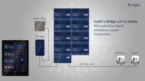
Wireless Network:
Rako Modules connect without wire via a WTC bridge with a rako module and wireless router which able to throw a signal to a wireless keypad and dimmer from where you can manage it either from your phone or tab.
Interface:
Multiple interfaces called Hub are available for the customer by rako according to their requirement.
- WTC Bridge
- WA Bridge
- WR B100
- WANEX
- RA Bridge
- RTC Bridg
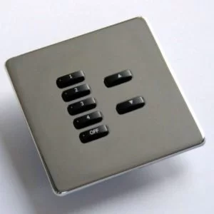
Keypads:
Rako offers flush and surfaced mounted plates which makes them very attractive and elegant.
Estimated Price of dimmers and keypads without interface.
| Dimmers Modules | Wireless & Wired Keypad |
| Rako RAK4T Dimmers = £506
|
Rako Wireless Flat faceplate Keypad RCM 020, 070, 100 = £125 ( 2, 7 & 10 button)
|
| Rako RAK4F Dimmers = £485 | Rako Wired Flat faceplate keypad WCM 020, 060, 070, 100 = £175 (2, 6, 7 & 10)
|
| Rako RAK4L Dimmers = £506 |
Lutron
Another system that can be say the best among the automation lighting control system in uk, lutran and rako do have a same technology from single room panel to a complete house, the only differences is the keypad design and the price.
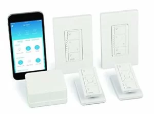
Lutron comes in the top list of lighting control system, it allows to you think each and every place you want to install at your home without limiting, regardless of the pre wires, you just don’t need it, Lutron offers individual wireless keypad, or if you want to install more than one room along with easy to manage, control via from phone or tab then a separate systems available offered by Lutron to be able to connect, communicate and integrate all switches, dimmers and other similar devices.
Lutron offers lighting packages according to room wise.
One room requires wireless switches but they only limit to digital control placed on a keypad, however if you want to manage from phone, tab or from remote then a separate controller will be needed to fulfill that task.
Number of packages and Plans available:
| One bedroom
|
Multiple Bedroom | Lighting Systems for one bedroom | Lighting Systems for multiple bedrooms |
| To save energy
|
Rania Wireless RF switch Radio Powr Savr – Occupancy/Vacancy Sensor |
HomeWorks QS | |
| To make a room more elegant and ambiance
|
Rania, Lyneo , Touch keypads
|
Radio Powr Savr sensors | |
| To be more convenient and remote control
|
Rania Wireless RF switch, Radio Powr Savr – Occupancy/Vacancy Sensor
|
HomeWorks QS | |
| To be more safe and secure | HomeWorks QS Sivoia QS |
||
| Pathway Lighting & multi-room control
|
HomeWorks QS | ||
| “Away” and “Vacation” Mode
|
HomeWorks QS Sivoia QS |
Fibaro:
 Fibaro make it easier for the customer to choose according to their requirement, it offers smart plugs with single switch panel to double switch panels, dimmers, smart sockets, sensors and RGBW controller, but here only the lighting control system will be in detail.
Fibaro not only best for new homes but it is one of the best home automation system that can be fit easily to an old sockets thanks to his small rectangular design, in addition the modulus size are very tiny only to be able to fit into the existing junction box easily.
Flexibility:
You can choose any place you want to fit, it can be fit in just single room with one socket or multiple rooms with multiple sockets you wants with the option of single button and double button panel.
Controller Hub:
Z-wave wall switch, plugs, dimmers and sensors cannot be handle and work alone without controller (hub), you need a controller Z-wave home center or certified controller from Z-wave to connect and manage all functions.
You could manage all switches at once via home center 1 or lite, it allows to integrate to all fibaro z-wave devices from one channel, in addition home center can be work with other devices such as Google home, Amazon Alexa, Apple Home kit and others devices certified by Z-WAVE from where you can control it remotely.
Fibaro lighting system packages:
- Smart Switches
- Smart Led Z-wave bulb, you can choose other Led to work with such as Philips hue.
- Dimmers modules 1 and 2
- Module Relays
- Inline switches
- Wall plugs and Sockets
Description and detail of all smart systems will be later in a separate section.
Caution: All smart lighting control system require neutral wire, most of the homes in UK do have neutral wires and but many not, so keep that confirm before installing that system.
Must be single switch panel if you intended to use only Apple Home kit
| APPLE Home Kit | Wireless Bluetooth communication | Simple scene sequences available | Apple Siri® voice control | Works with iOS 9 and higher | The sharing home functionality |
Double switch panel work with Z-WAVE and other controllers.
| Z- Wave | Wireless Z-Wave communication | Simple scene sequences available | Smart notifications
|
Works with iOS 9 and higher | Wide operating range |
Futronix
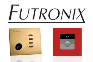
Designed especially for old homes, available only as a wired technology with a replacement of old panels and buttons, Futronix systems is prewired small compact design panels to make it fit in existing installation.
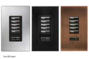
Futronix offers stainless steel and Sahara design switch panels and dimmers with the configuration of 2 button panel to up to 12 button panels.
To control and manage all, Futronix offers dedicated controllers with wired and wireless technology.
Futronix can be integrate with Amazon Alexa to be able to control lighting from voice, home icon touch screen and remote control for lighting can be get as an extra.
Estimated Price:
| Dimmers | Switches | House controllers |
| P100 dimmer = £ 160 | Eclipse Switch panel = £ 306 Pound | Futronix Hx System = £ 993 |
| P400 dimmer = £ 349 | Metal Switch plate = £ 154 | Futronix Home Automation =
£ 1160 |
| P800 dimmer = £ 714 |
Control
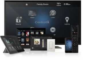
Control 4 is very similar to Lutron smart lighting, very stylish, elegant
and reliable for long durability is a key to this company.
Control 4 enable you to control lights by voice with Alexa and google home, if offers you a complete range of wired and without wired lighting and dimming control systems.
Control 4 has wireless keypads, dimmers, switches and wired keypads with variety of button and face plate colors you can choose.
Compatible Led:
Perfect for Dimming
- SYLVANIA HI-spot RefLED PAR-16 GU10 – 6.5W
- Osram Parathom PRO PAR-16 50 Advanced
- Philips Master LEDspot MV 6W GU10 dimmable
- Megaman LED Reflector GU10 – 7W 500lm
- Megaman Energy saving LED reflector PAR16 8W
- BELL Mini Dimmable 5W LED GU10 Stock Code 05136
- BELL Dimmable 8W LED GU10 BC/B22
There are few of the best LEDs which support all smart automation systems.
Note:
These four are so far the best for Home automation lighting control system in uk, if you want to choose other than these due to low budget, then I would suggest to keep that project step aside until you have the budget to cover one of these systems cost fulfill, however in spite of other low price systems are available, but not durable for long life, for single room or to make a dimmer lamp or to do only an experiment then there is another article which suggest that about getting started with home automation lighting control.
About The Author
Hassan Zaka
I am an expert in accounting and possess diverse experience in technical writing. I have written for various industries on topics such as finance, business, and technology. My writing style is clear and simple, and I utilize infographics and diagrams to make my writing more engaging. I can be a valuable asset to any organization in need of technical writing services.
Follow Us:LinkedinTwitter


