Aquarium Light V1

Photo of author
Written By Hassan Zaka

I'm an experienced expert in accounting and technical writing, skilled at simplifying complex topics with engaging visuals. Ideal for any organization in need of top-tier technical writing services.

My first attempt at an LED Aquarium Light V1 started as an excuse to buy some of those LED light strips off of eBay.  I gutted the old 18″ fluorescent fixtures and soldered together row after row of 18″ RGB LED strips.  They mounted to a thin aluminum plate I screwed into the old light housings Aquarium Light V1.  I mounted one of those remote-controlled RGB LED controllers in there with a 12V 5A power brick.  The remote control let us change the colors, and had a few blinky light modes that I’m sure the fish didn’t appreciate too much.  My wife loved it, which is all that really matters.
Aquarium Light 1
I wasn’t happy with the overall build – the fixture was fairly hot and the adhesive backing on the LED strips was worthless.  I eventually had to encapsulate the LED strips with a sheet of polycarbonate on the front to keep them from falling off, which made everything even hotter.  The project died one day when the combined heat of the LEDs and the power brick melted a big smelly hole right through the brick’s black plastic housing.  I wasn’t home so I can’t say whether any flames were involved, but the polyurethane coating encapsulating the LEDs was browned in several places.  We were pretty lucky nothing fell into the water and poisoned the fish.
Aquarium Light 2
At this point I was ready to drop $150 on some aquarium light from Amazon, but my wife loved the ambiance of the RGB LEDs so much she convinced me to make a better one.  I coiled a white LED strip on top of the aquarium without a housing.  It looked pretty bad but that way it wouldn’t get so hot and the fish wouldn’t be left in the dark while I figured things out.

Version 1

Aquarium Light

I knew heat was my biggest enemy, yet I wanted to make something significantly brighter than the old LED strips could achieve.  I read all about the intensity of light at sea level and what kind of lighting a planted aquarium might require.  Eventually I decided to go with six 30W RGB LEDs, which I could find on eBay for about 12 dollars each.  That’s a total of 180W of heat that the fixture would need to dissipate.
Aquarium Light
I spent a few weeks searching the internet for an appropriate housing.  Eventually I found a website called gkphotonics.com which sells extruded aluminum project boxes of various shapes and lengths.  The 4″ wide profile looked great and was the perfect size for my aquarium.  It also had grooves on the inside which could hold a circuit board.  I contacted the owner and he was able to make me a 48″ long piece anodized black.  It took a few weeks, but it eventually arrived in good condition and for less than $100 including shipping.
To help dissipate the heat, I added a fan to one end of the extrusion.  It pulls air in from the area where the LEDs are mounted and pushes the air through the extrusion and out of the other end.  The opposite end cap was raised off the extrusion by a few millimeters to allow the air to escape.  Small aluminum U-channels were screwed into the bottom edges to make space for the LEDs to mount underneath.  I had to cut a few slots in them to avoid interference with the Aquarium’s hood pieces.

Driving the LEDs

Driving the LEDs

Driving the LEDs 1

I needed a power supply and driver circuits to power 18 LEDs at 300-350ma each.  It also needed to power the cooling fan and the Arduino.  The Green and Blue LEDs run at 32V nominal, while the Red LEDs run closer to 24V.  Surfing around eBay I found 36V open frame power supplies with 10 A current rating could be purchased for around $35.  I decided to go with a single 36V supply for everything.  The first one that came was DOA, but I contacted the seller on eBay and they promptly sent a replacement which worked.  The power supply would be external to the aluminum extrusion, mounting somewhere underneath the tank.  Finding a power cord was not a problem, as I have a whole box of cords which have been harvested from broken appliances over many years.
Driving the LEDs
I considered using series resistors to regulate the LED current, but that would only provide 3-4V drop across the Blue and Green LED resistors, which probably wouldn’t be enough to prevent thermal runaway.  In my search for constant current regulators I came across a circuit which uses a MOSFET transistor as an LDO current regulator.  To achieve current regulation, one current sense resistor and one NPN transistor are required.  The MOSFET is normally held in an On state by a pullup resistor, allowing current to flow through the LED.  As the current through the current sense resistor increases, the voltage at the base of the NPN transistor increases.  At around 0.6V, the NPN transistor turns on and pulls the MOSFET gate voltage down to ground.  This decreases the current flowing in the circuit, until the base of the NPN transistor is back to 0.6V.  By selecting a current sense resistor of 1.8 ohms, the circuit will maintain 333ma of current.  One benefit of using a MOSFET is that they typically can withstand 175C junction temperatures, whereas most standard LDO regulators can only handle 125C.  By adding an extra PNP transistor between the MOSFET gate and ground, I could turn the circuit on and off with a micro-controller.
Driving the LEDs 2
I still needed to use an LED series resistor in the circuit, since the MOSFET would burn itself up if it tried to absorb the entire 333 ma at 12V drop needed for the Red LED.  I ordered one LED from eBay and played with it until I figured out what size of series resistors would be needed to minimize the dissipation within the MOSFET.  The Blue and Green LEDs were so close that the same resistor value could be used, but the Red LED required a much higher value.  The power dissipated in the Red LED series resistor would be nearly 4W at full power, so I decided to use 10W sandstone types for all of them.
Driving the LEDs 4
Driving the LEDs 4
I designed the two-sided circuit board in Eagle.  One PCB would handle 6 LED channels, so a total of 3 PCBs would need to be made.  I tried to leave as much copper as possible to aid with heat dissipation.  I used the toner transfer method with lots of ironing to transfer the traces onto the copper clad board.  The boards were etched in muriatic acid and hydrogen peroxide.
Connections to the LEDs were made using 4 conductor telephone wire with a bright yellow jacket.  Since the LEDs mount on the outside, I potted the exposed LED tabs with epoxy after soldering the wires on to prevent shorts.  I used screw terminals for all the high current connections at the PCB.  Pin headers and 6 conductor Dupont cables connect the LED driver boards with the Arduino.
I started off using small SOT223 LDO regulators to step the 36V supply down to 12V to power the cooling fan, drive the MOSFET gates, and power the Arduino.  After testing for a few minutes, groups of LEDs would shut off, and pretty soon the whole thing would stop working.  I eventually figured out that I hadn’t sized the regulators to handle the load and they were going into thermal shut-down.  I began looking at switching regulators and found the LM2576 datasheet.  I ordered the switcher and a few caps and coils from Digikey and built the regulator on a piece of perf board.  After installing the new regulator all of the thermal shutdown events went away.
By the time all of the boards were wired up to each other, there was quite a rats nest of wiring to deal with.  I spent too much time twisting and bundling the wires together so they wouldn’t hang up on each other when sliding all the boards in.  The Arduino was the last board to slide in, so that the USB port would be accessible from the outside for reprogramming.  I desoldered the barrel jack from the Arduino to avoid making extra holes in the end plate.

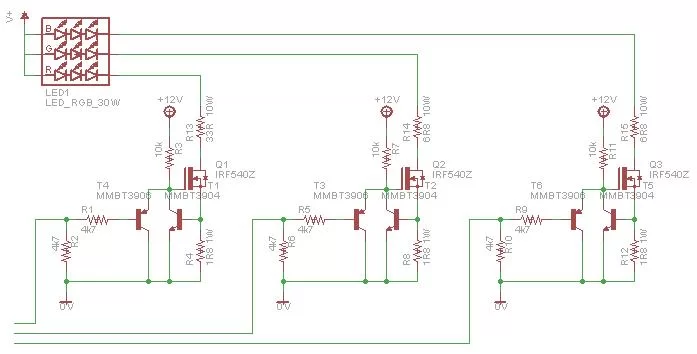
Controlling the LEDs

While version 0 could only produce one color at a time, I wanted to be able to generate any kind of rainbow light show I could imagine, or even simulate the shadows of clouds passing by overhead.  That meant I needed to control all 18 LED channels independently.  I also wanted a potentiometer to control the overall brightness of the light, and a button so I could put it into different light modes.  With the addition of an RTC, I could have a light that would automatically run different modes at different times of day, eliminating the noisy mechanical timer sitting in the cabinet below the tank.  The blower fan which keeps everything cool was just a little bit too noisy at full speed, but I found that I could PWM its supply voltage at certain frequencies to control the speed and reduce the noise.  I added a temperature sensor close to one of the LEDs so that I could turn up the fan speed if the LEDs became too hot.
By far the biggest challenge was figuring out how to PWM 18 channels.  The Arduino Mega can support up to 16 channels of PWM, which wasn’t enough.  I started playing around with bit-banging PWM signals to see if that might do the trick.  I figured I wanted to keep at least 8 bit resolution, and I needed at least 120 Hz to 180 Hz to avoid any strobe effects when the fish swim around.  After reading a lot about direct port access, I was able to put together some code that could bit-bang PWM 18 channels at around 200 Hz.  Once everything was built and I began testing, I noticed that even 200 Hz wasn’t sufficient to prevent the air bubbles from looking like a strobe.  I went all out timing every single line of code and optimizing everything until I had the PWM loop running at 1000 Hz while maintaining 256 steps.  The result is fairly simple, but I tried dozens of different things before I was happy.

Bit-Banging 18 Channels at 1000 Hz

void BitBangLEDsOn() { // 944 us
    byte sawtooth = 255;         // start sawtooth at 255 and decrement to 0
    while (sawtooth > 0) {
      if ( scaledCurrentBrightness[12] == sawtooth )  PORTC |= B00100000;          // LED Array Index 12 = PORTC PIN5
      if ( scaledCurrentBrightness[13] == sawtooth )  PORTA |= B00010000;          // LED Array Index 13 = PORTA PIN4
      if ( scaledCurrentBrightness[14] == sawtooth )  PORTC |= B00010000;          // LED Array Index 14 = PORTC PIN4
      if ( scaledCurrentBrightness[15] == sawtooth )  PORTA |= B00100000;          // LED Array Index 15 = PORTA PIN5
      if ( scaledCurrentBrightness[16] == sawtooth )  PORTL |= B00010000;          // LED Array Index 16 = PORTL PIN4
      if ( scaledCurrentBrightness[17] == sawtooth )  PORTG |= B00000100;          // LED Array Index 17 = PORTG PIN2
      if ( scaledCurrentBrightness[ 0] == sawtooth )  PORTC |= B00000010;          // LED Array Index  0 = PORTC PIN1
      if ( scaledCurrentBrightness[ 1] == sawtooth )  PORTC |= B10000000;          // LED Array Index  1 = PORTC PIN7
      if ( scaledCurrentBrightness[ 2] == sawtooth )  PORTC |= B00000001;          // LED Array Index  2 = PORTC PIN0
      if ( scaledCurrentBrightness[ 3] == sawtooth )  PORTC |= B01000000;          // LED Array Index  3 = PORTC PIN6
      if ( scaledCurrentBrightness[ 4] == sawtooth )  PORTL |= B00000001;          // LED Array Index  4 = PORTL PIN0
      if ( scaledCurrentBrightness[ 5] == sawtooth )  PORTL |= B01000000;          // LED Array Index  5 = PORTL PIN6
      if ( scaledCurrentBrightness[ 6] == sawtooth )  PORTC |= B00001000;          // LED Array Index  6 = PORTC PIN3
      if ( scaledCurrentBrightness[ 7] == sawtooth )  PORTA |= B01000000;          // LED Array Index  7 = PORTA PIN6
      if ( scaledCurrentBrightness[ 8] == sawtooth )  PORTC |= B00000100;          // LED Array Index  8 = PORTC PIN2
      if ( scaledCurrentBrightness[ 9] == sawtooth )  PORTA |= B10000000;          // LED Array Index  9 = PORTA PIN7
      if ( scaledCurrentBrightness[10] == sawtooth )  PORTL |= B00000100;          // LED Array Index 10 = PORTL PIN2
      if ( scaledCurrentBrightness[11] == sawtooth )  PORTG |= B00000001;          // LED Array Index 11 = PORTG PIN0
      sawtooth–;
    }  // END PWM WHILE LOOP
}
void TurnAllLEDsOff() { // 4 us
    PORTA &= B00001111;  // Turn Off PORTA bits 4 – 7
    PORTC &= B00000000;  // Turn Off PORTC bits 0 – 7
    PORTG &= B11111010;  // Turn Off PORTG bits 0, 2
    PORTL &= B10101010;  // Turn Off PORTL bits 0, 2, 4, 6
}
I programmed a number of sub-routines which needed to be interleaved between all the bit-banging.  These include calculating the LED brightness trajectory, checking the mode input button, reading the potentiometer, monitoring the temperature, controlling the fan speed, retrieving the time from the RTC, and comparing the current time with the list of modes.  Many of the routines were split up into several shorter functions.  The longest routine was under 250 microseconds in duration, which helped to avoid any visual flicker of the LEDs.  The functions were called only when necessary using a scheduler.
I spent a lot of time figuring out how to define each mode and and how to smoothly transition from one to the next.  I wanted a slow sunrise mode in the morning, a bright white mode during the day, some kind of fading rainbow mode during the evening, a slow fade sunset mode, and a dark blue late evening mode, followed by an off mode for the late night until morning.  I wanted a way for the sunrise and sunset modes to automatically transition to the appropriate next mode, and I needed a scheduler to interrupt the current mode and set the next mode at certain times of the day.  For each mode, I wanted to have a list of “waypoint” brightness values for each LED, and the program would set the brightness of each LED by linearly interpolating between the waypoints.  The duration of time that would elapse between each waypoint could also be specified.
The modes list ended up being a list of structures.  Each structure contains a list of waypoints containing the brightness value for each LED, the number of waypoints in the mode, the number of 1 millisecond steps in between each waypoint (i.e. the duration of time between waypoints), and what the next mode should be.

Defining the Modes

typedef struct{
  byte modeBrightnessValues[maxBrightnessValues];
  unsigned int  modeNumBrightnessStates;
  unsigned long modeNumSteps;
  unsigned int  modeNextMode;
} MODE;
 
MODE modesList[numModesTotal];
Below is mode #7, which is the sunset mode.  For this mode, 5 waypoints are specified.  These waypoints step through different colors of a sunset.  The first 18 values in the list describe the starting condition as bright white.  The program will interpolate the LED colors and brightness between the initial bright white, to the second waypoint, which is sunset yellow.  The program will continue interpolating between the different colors of each waypoint until the final waypoint which is dark blue.  At that point, the program will jump to the next mode, which is defined as mode #4 – the dark blue late evening mode.  With 900,000 steps between each set of waypoints, it will take 1 hour for the program to complete the sunset mode.

Mode 7 – Sunset

modesList[7] = (MODE) 
{{255, 255, 255, 255, 255, 255, 255, 255, 255, 255, 255, 255, 255, 255, 255, 255, 255, 255,  // White
  250, 250, 250, 250, 250, 250, 214, 214, 214, 214, 214, 214, 165, 165, 165, 165, 165, 165,  // Sunset Yellow
  240, 240, 240, 240, 240, 240,  94,  94,  94,  94,  94,  94,  83,  83,  83,  83,  83,  83,  // Sunset Orange
  120, 120, 120, 120, 120, 120,   5,   5,   5,   5,   5,   5,  64,  64,  64,  64,  64,  64,  // Sunset Purple
    0,   0,   0,   0,   0,   0,   0,   0,   0,   0,   0,   0,  64,  64,  64,  64,  64,  64}, // Dark Blue
  5,900000,   4}; // 1ms * 900,000 steps = 15 minutes each
Mode #2 is what I call the travelling rainbow.  There are 13 waypoints, with the last waypoint being identical to the first.  Each color of each LED follows a 12 step sinusoidal trajectory, with each of the three colors 120 degrees out of phase.  The effect is that the colors appear to travel slowly from one end of the light to the other.  With 10 seconds between waypoints, it takes 2 minutes to cycle through all the colors, traveling from one end down to the other.  The mode references itself as the next mode, so it will continue running until the scheduler decides it is time to change the mode to something else.  The pictures at the top and bottom of this page show the light operating in Mode 2.

Mode 2 – Travelling Rainbow

modesList[2] = (MODE) 
{{191, 237, 255, 237, 191, 127,   0,  18,  64, 127, 191, 237, 191, 127,  64,  18,   0,  18,  // 
  237, 255, 237, 191, 127,  64,  18,  64, 127, 191, 237, 255, 127,  64,  18,   0,  18,  64,  // 
  255, 237, 191, 127,  64,  18,  64, 127, 191, 237, 255, 237,  64,  18,   0,  18,  64, 127,  // 
  237, 191, 127,  64,  18,   0, 127, 191, 237, 255, 237, 191,  18,   0,  18,  64, 127, 191,  // 
  191, 127,  64,  18,   0,  18, 191, 237, 255, 237, 191, 127,   0,  18,  64, 127, 191, 237,  // 
  127,  64,  18,   0,  18,  64, 237, 255, 237, 191, 127,  64,  18,  64, 127, 191, 237, 255,  // 
   64,  18,   0,  18,  64, 127, 255, 237, 191, 127,  64,  18,  64, 127, 191, 237, 255, 237,  // 
   18,   0,  18,  64, 127, 191, 237, 191, 127,  64,  18,   0, 127, 191, 237, 255, 237, 191,  // 
    0,  18,  64, 127, 191, 237, 191, 127,  64,  18,   0,  18, 191, 237, 255, 237, 191, 127,  // 
   18,  64, 127, 191, 237, 255, 127,  64,  18,   0,  18,  64, 237, 255, 237, 191, 127,  64,  // 
   64, 127, 191, 237, 255, 237,  64,  18,   0,  18,  64, 127, 255, 237, 191, 127,  64,  18,  // 
  127, 191, 237, 255, 237, 191,  18,   0,  18,  64, 127, 191, 237, 191, 127,  64,  18,   0,  // 
  191, 237, 255, 237, 191, 127,   0,  18,  64, 127, 191, 237, 191, 127,  64,  18,   0,  18}, //
  13,10000,   2};  // 1ms * 10k Steps = 10 seconds between states. Next Mode = 2.
This was a fantastic project for learning about data types and how to write faster embedded code.  I learned a lot about data structures, direct port access, bit shifting, casting, avoiding division, when to use a byte instead of an int, and when to just write it all out instead of using extra loops.

Conclusion

onclusion
onclusion
I started the project in October 2012 and finished in February 2013 with a total cost of around $400.  As of May 2014 the light is still running strong and our aquarium is the center piece of the living room.  I have taken the light to several meetings and events with the Atlanta Hobby Robot Club and have been asked several times where I bought it – apparently it looks too good to have been a DIY project!
There is one caveat I have with the concept of an RGB LED Aquarium light.  After using the light for a while I noticed significantly more algae growth in the tank, much more than the big Pleco and a few small Otocinclus fish are able to keep up with.  On the positive side, our Anubias plant has been growing really fast since the light was installed.  I’m not sure if this is because there is so much more light than there used to be, or if it has to do with the spectral concentration in the Red and Blue wavelengths.  We may need to invest in a few more plants to soak up all the rays.

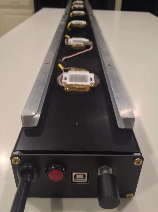
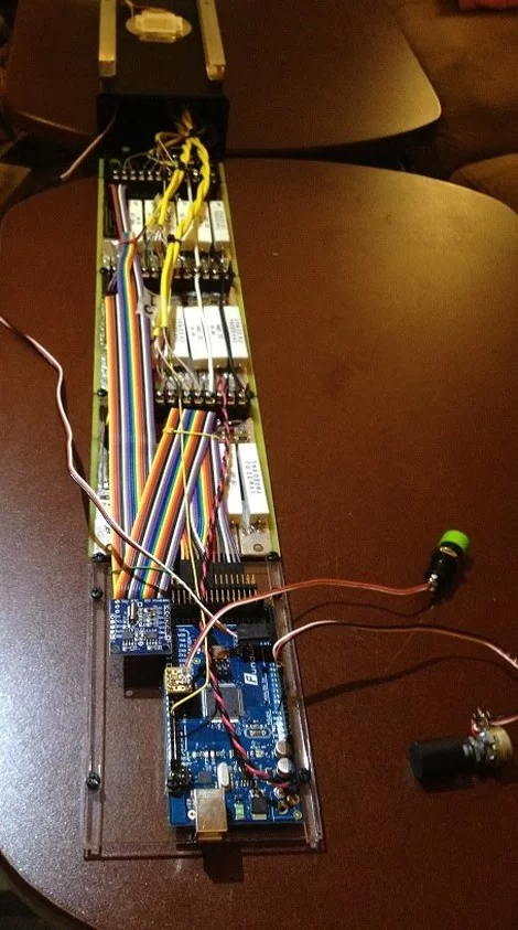
When running at full power, the housing right around the LED driver circuitry can become uncomfortable to the touch, and is much cooler down at the other end where the fan is mounted.  It appears as if the major problems of Version 0 have been solved.  While LEDs are generally quite efficient, I’m not thrilled about wasting 24 Watts just to step the voltage down to the red ones.  I’m sure some future project will tackle this and several other opportunities.

If you like this project or have any suggestions, send me a note, I’d be glad to hear from you.
0/5 (0 Reviews)

Leave a Comment