Waking up to a Bubble Alarm Clock sucks. I’m one of those people who doesn’t like to wake up before the sun is out (or has been out for many hours). So what better way to make waking up fun than having a bubble party in bed!
Using an arduino and a commonly available bubble machine toy, you too can wake up to the joy of bubbles.
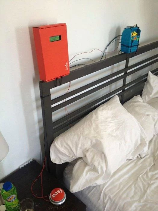
Take a look at the alarm in action:
[mom_video id=’DvkSnIRKXU8′]Step 1: Tools & Materials

The Parts (you can definitely substitute for stuff you have around the house):
Bubble generating toy: Super Miracle® Bubbles Bubble Factory (purchased at Michaels for 12 bucks)
Microcontroller: Arduino (old Seeduino in my case)
LCD display: Sparkfun Basic 16×2 Character LCD
Snooze button: Staples Easy Button
LED: ThingM BlinkM
Transistor: TIP-120 (Radio Shack 276-2068)
Relay: 5V SF COM-00100
Assorted buttons/switches to adjust time: SF COM-09190 & SF COM-00102
Potentiometer: SF COM-09806
Perfboard
Diode (1N4001)
Resistor 2.2K
Wire
Power adapter for arduino
Pin headers
Tools
Soldering iron
Wire Strippers
Zip Ties
Dremel
Multimeter
Breadboards
Step 2: Break Open the Bubble Machine
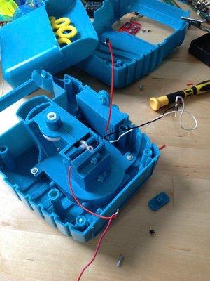
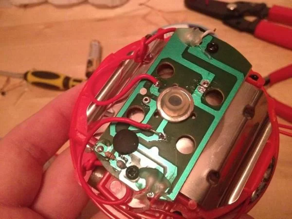
First you’ll need to open up the bubble machine. The one I found was easy to open, just four philips head screws.
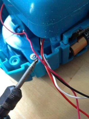
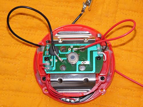
Once inside, disconnect the battery and motor from the switch and solder wires for both the motor and the battery pack long enough to feed outside of the machine.
Next, use a Dremel tool to make an opening in the plastic to feed the wires out.
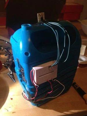
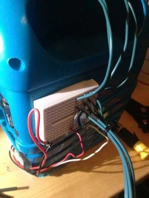
If you like colorful bubbles, attach the LED or ThingM BlinkM on the top of the machine.
Finally, I opted to place a mini-breadboard on the back of the bubble machine to collect all the wires. This made it easier to adjust the distance between the controller and the unit.
Step 3: Prepare the Easy Snooze Button
Essentially you need to remove a capacitor and resistor and attach your own wires.
The easy button is, uh, easily opened by removing the plastic feet to access the four philips head screws. Be sure to hang onto the feet.
Big buttons rock.
Step 4: Prototype the Circut
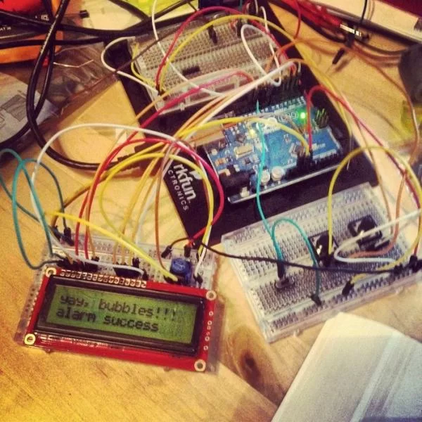
Plugging stuff in
Depending on the LCD you choose, there may be different wiring requirements.
For the Sparkfun Basic 16×2 Character LCD & using the LiquidCrystal.h library Using the LCD library and following the data sheet (http://www.sparkfun.com/datasheets/LCD/GDM1602K.pdf)
Here is a wiring diagram:
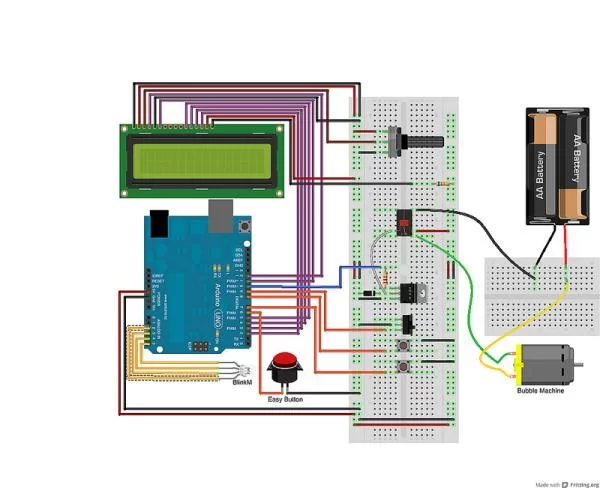
Originally I was planning to run the motor directly from the transistor. It seems that the motor produces a significant amount of noise in the ground, causing the LCD to print garbage. I switched to a relay to keep the motor and Arduino circuits separate.
I wasn’t familiar with making this type of circuit. These resources were helpful, you might want to check them out.
High-Power Control: Arduino + TIP120 Transistor
ITP Physical Computing Tutorial: Using a transistor to control high current loads with an Arduino
Step 5: Write the Code
Here is a GitHub Repository of the current code I’m using. It needs a bit of work, but it should get you going.
https://github.com/tomarthur/Bubble-Clock/
The current version of the alarm clock uses the Time.h Arduino library to provide the basic time keeping.
Improvements to be made in the future:
– Incorporate an external time keeping device or even a GPS based time clock, avoiding the loss of the time & alarm if the Arduino looses power
– Allow time to be set remotely, or different alarms for different days of the week
– Method for activating bubbles for fun (secret snooze button tap sequence?)
Step 6: Build the Circuit on Perfboard
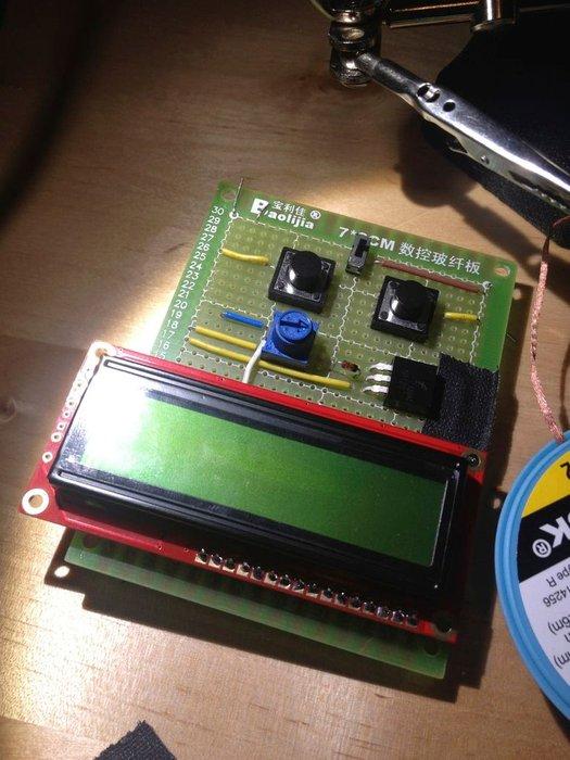
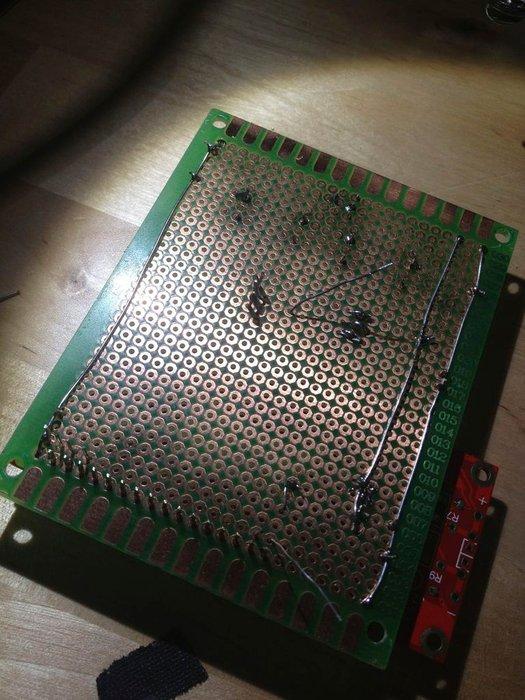
Once you have a working circuit on the breadboard, it’s easy to transfer everything over to perfboard to build a more permanent setup. I happened to have a couple pieces sitting around, but you can also find boards that are similar to breadboard designs, making moving the circuit easier.
Because no holes are connected on this type of board, I wired a ground and +5V wire down the side.
I originally soldered the LCD directly to the perfboard. Bad idea! It made troubleshooting difficult. The second time around I soldered female pin headers to the perfboard so the LCD can be removable.
Step 7: Test & Adjust
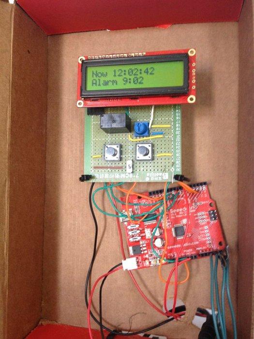
Once you have finished the perfboard circuit, connect it to your Arduino. Once everything seems to be working you can mount the bubble machine and controller in your bedroom.
I ended up using an extra box to mount the microcontroller on the bed frame for the time being.
About The Author
Hassan Zaka
I am an expert in accounting and possess diverse experience in technical writing. I have written for various industries on topics such as finance, business, and technology. My writing style is clear and simple, and I utilize infographics and diagrams to make my writing more engaging. I can be a valuable asset to any organization in need of technical writing services.
Follow Us:LinkedinTwitter