Overview of Node Red Home Automation
Node-RED, developed by IBM, is a browser-based visual flow editor for IoT and home automation that integrates well with Home Assistant. The article explains Node-RED features, compatible hardware, and contrasts it with Home Assistant YAML automations. It provides two detailed projects: a Raspberry Pi Node-RED UI-driven home automation and a standalone Pi + Sonoff/ESP8266 + MQTT system (with Sonoff-Tasmota flashing, Mosquitto MQTT setup, Node-RED dashboard, security, and expansion ideas). Step-by-step installation, wiring, Node.js/npm fixes, MQTT testing, dashboard setup, Sonoff programming, and securing the broker are covered.
Quick Solutions to Questions related to Node-RED Home Automation:
-
How do I install extra UI nodes for Node-RED on Raspberry Pi?
Run cd ~/.node-red then npm install node-red-contrib-gpio and npm install node-red-contrib-ui, then restart Node-RED. -
Can Node-RED communicate with an MQTT broker on the same Pi?
Yes; configure MQTT nodes with server localhost and topics, deploy, and you will see connected status and payloads exchanged. -
What are the steps to secure Mosquitto MQTT for Node-RED and Sonoff devices?
Stop Mosquitto, create/edit /etc/mosquitto/conf.d/mosquitto.conf to disallow anonymous and set a password_file, add users with mosquitto_passwd, then restart Mosquitto. -
How do I flash Sonoff devices with Sonoff-Tasmota using Arduino IDE?
Set up a separate Arduino folder, install Sonoff-Tasmota, configure board settings, connect USB serial programmer, hold Flash/GPIO0 low during upload, and send WiFi/MQTT settings via serial or web mode. -
Best way to make Node-RED start automatically on Raspberry Pi boot?
Enable the service with sudo systemctl enable nodered.service so Node-RED runs at boot and restarts on crashes.
Node-RED is a development team created by IBM for IoT devices and is the perfect companion to a home automation platform such as Home Assistant. At its core, it allows for easy automation of virtually any connected device or service in an easy to understand visual flow interface composed of nodes and wires.
It provides a browser-based editor that makes it easy to wire together flows using the wide range of nodes in the palette that can be deployed to its runtime in a single-click.

Features of Node Red
- Node-RED provides a browser-based flow editor that makes it easy to wire together flows using the wide range of nodes in the palette.
- Flows can be then deployed to the runtime in a single-click.
- JavaScript functions can be created within the editor using a rich text editor.
- A built-in library allows you to save useful functions, templates or flows for re-use.
- The light-weight runtime is built on Node.js, taking full advantage of its event-driven, non-blocking model.
- An online flow library allows you to share your best flows with the world.
Compatible Hardware for Node Red Home Automation
Computer
Device
Cloud
Comparison between Home Assistant vs Node Red
- Home Assistant comes with it’s on YAML based automation capabilities. You can craft automation via the front-end or directly in the automations.yaml file. There’s nothing wrong with this approach, it’s just not visual and can be quite tedious as anyone who’s worked with YAML knows… one extra space can brick your setup and force you to go line by line looking for the offense.
- If you go the Node-RED route, it essentially just executes logic against Home Assistant’s state machine, which just keeps track of all your sensors and devices and their respective status (e.g.,kitchen motion sensor is on, bedroom light is off).
- For those not interested in coding, Node-RED is definitely more powerful given its many nodes and powerful integrations with other platforms such as Telegram for notifications. That said, it’s never a bad idea to learn the basics of a language like Python or Java and you can create extremely sophisticated automation with a bit of code.
Related: Home Assistant Vs Openhab 2019
Decisive Stage
If you still unsure about what to use either home assistant or Node red or very knew to its field then. Home Assistant is one of the most flexible and sophisticated open-source smart home platforms, and Node-RED is a visual programming tool making rule creation a walk in the park (ish). It can work on our pick how you should spend first $250 on smart home, allowing you to create rules and experiment with all seven devices included.
So let’s get started with Node Red home automation
Related : Open Source Home Automation Solutions
[highlight bgcolor=”#237fdb” txtcolor=”#ffffff”]Project 1 with Node Red Home Automation[/highlight]
Home Automation using Raspberry Pi 2 and Node-RED

- Lamp 1
- Lamp 2
- Fan
- Tv
- Night dimmer
- Motion Sensor
Hardware components
- Raspberry Pi × 1
- LED (generic) × 2
- 5 V, 4 Channel Relay Board × 1
- PIR Motion Sensor × 1
- Resistor 330 ohm × 2
Set up Raspberry Pi on the network and update the distribution. You can run the following commands in terminal for that:
[highlight bgcolor=”#1e1e1e”]
sudo rpi-update
sudo reboot
[/highlight]
After reboot execute following commands:
sudo apt-get update
sudo apt-get upgrade
At the end of the project, final user interface of this project will be looking like the following:
[image link=”4362″ image=”4362″]
[image link=”4363″ image=”4363″]
[/images]
This application runs in web browser, so you don’t need to install any extra application to play with it and you can run it from any smart phone, tablet or from a PC which has a web browser. And as for what this project is concerned, you can automate your home within your home network only. You can extend functionality of the system but I am not going to explain it in this project.
For this project, first you will need to set up Node-RED on a Raspberry Pi 2.
Installing Node-RED on Raspberry Pi
There are two ways for this:
- There is pre-installed Node-RED in the November 2015 Raspbian Jessie image. Go to: Menu->Programming->Node-RED.
- Or you can install it manually. A very good documentation available for that and you can find it
Running Node-RED
After setting everything up, the next step is to run Node-RED. You can run it from the Menu or by the following command in terminal:
Node-red-start
Node-red-stop (to stop Node-RED)
If you want to work on the Raspberry Pi desktop, then open the web browser and enter the address you may find as shown in following image after running Node-RED:

Or the second option (much better than working on local host) is to open web browser in any other PC (faster than Raspberry Pi) connected to your home network and enter the address as you can find shown in following picture.

Open the web browser and enter the address of your Raspberry Pi, in my case it is: 192.168.1.12:1880
If everything is correct then you will find following result:

As you can see in the left side there are many different nodes, and I am going to use some of them for this project. Just Drag and Drop to use them.
Installing some extra nodes for UI
For this project you need to install some extra nodes to your Raspberry Pi and it is very simple, just enter following commands in terminal:
cd ~/.node-red
npm install node-red-contrib-gpio (Documentation)
npm install node-red-contrib-ui (Documentation)
After running these commands, I recommend to stop and restart the Node-RED so it can update the node list.

Now it is time to create the UI and and coding in Node-RED
To create Flow watch this video.
Hardware Set Up
Connect the hardware components to proper pins as you defined in Node-RED. Check schematic section for circuit diagram.
Output
If you have done everything correct then you will find the result as in this video.
Now you can control your home devices by web browser in your smart phone, tablet or computer.
[highlight bgcolor=”#237fdb”]Project 2 with Node Red Home Automation[/highlight]
Stand Alone System Pi, Sonoff, ESP8266 and Node-Red

The steps are:
- Load a Pi with Rasbian Stretch
- Update and add features to Node-Red
- Install the Mosquitto MQTT broker
- Set up the Arduino environment for uploading the Sonoff-Tasmota firmware
- Re-program a Sonoff switch
- Set up the Node-Red interface
- Test it all works.
Hardware you will need:
- Raspberry Pi and power supply (and keyboard and monitor for initial setting up) (model B used here)
- Sonoff Switch
- USB Serial converter
- Optional – ESP development board such as the NodeMCU.
Step 1: Load a Pi with Raspbian Stretch
This should be pretty straightforward. Start with an 8Gb or 16Gb SD card. Download the latest version from:
https://www.raspberrypi.org/downloads/
The main thread here assumes that the full version is loaded. However you can use the lite version to save space. If using Raspbian Stretch Lite proceed through this step and then go to Step 9 at the end.
Unzipping the downloaded file gives a folder with the .img file. 7Zip is recommended for Windows (and The Unarchiver Mac). The image has to be burned onto the SD card – but a special program has to be used as the file system is not compatible with Windows. The recommended software is called Etcher and can be downloaded from:
The instructions for Etcher are on their website and could hardly be simpler. Select the image and the drive and click Flash.
Now with our flashed SD card with can get the Pi running.
If you know the IP address your Pi uses or are happy to find it by logging on to your router then you can avoid the need for keyboard and monitor and use SSH immediately. Just add a blank file named SSH to the SD card, insert, connect to Ethernet and power up. Otherwise follow the guide below.
Connect the Pi to internet, screen, mouse and keyboard and connect to power. The first thing we will do is enable SSH so we can do the majority of the setup from the comfort on a PC. It can of course be done direct but it helps a great deal to be able to follow this guide on the same device as one driving the Pi and use copy and paste for most of the instructions.
There is a guide for a good deal of the work on a YouTube video. This is where I started. You can run the video alongside following these instructions.
The video starts with showing what Node Red can do, and then covers the Pi install and setup, followed by upgrading Node Red and lastly installing Mosquitto.
- 00:00 Introduction to Video
- 03:00 Node Red demonstration
- 14:14 Importing dashboard items into Node Red
- 21:05 Pi initial setup, including SSH
- 23:35 Installation of Node Red supporting code
- 27:00 Introduction to MQTT
- 29:12 Mosquitto (MQTT) installation (Note only works for Raspian Jessie)
- 33:00 Node Red examples
Step 2: Update and Add Features to Node-Red
NODEJS PROBLEM
We have been hit (1st Nov 17) by an update of Nodejs that is incompatible with npm. If node-v gives v9.0.0 then you have the incompatible version.
The procedure here has now been updated to give the latest working combination of node and npm. (8.9.0 and 5.5.1 respectively)
If node v9.0.0 loaded you can downgrade by:
sudo n 8.9.0
sudo shutdown -r now
Log on after restart and check versions by:
node -v
npm -v
If you want to be thorough now also do:
sudo n rm 9.0.0
This removes the 9.0.0 version data from the install folder.
Step 2 of 3
The PuTTY connection will have been lost by the restart at the end of the previous step. So close PuTTY and after waiting for the Pi to boot, Log on again as before.
sudo apt-get install npm
Y
sudo npm i -g npm@2.x
Note this takes a while…..
npm -v
-should give 1.4.21
node -v
– should give 4.8.2
sudo npm install -g n
sudo n 8.9.0
sudo shutdown -r now
The PuTTY connection will be lost. So close PuTTY and after waiting for the Pi to boot, Log on again as before.
node -v
– should give v8.9.0
- npm -v
– should give 5.5.1
These latter instructions show the installed versions and that our upgrades have been installed.
So at this point we have our pi loaded and updated and with the updates needed for Node Red. It is no harm to do a restart before the next stage.
sudo shutdown -r now
Step 3: Mosquitto MQTT Installation
If you have not already done so it is worth viewing the video introduction to MQTT on the video from 27:00.
This is where we need to take a different path. The procedure outlined in the video only works for the older Jessie version of Raspbian. There is a discussion on the mosquitto site but no clear outcome shown and hence will stick to a simpler and safer route.
So log on using PuTTY and enter the following:
sudo apt-get update
sudo apt-get install mosquitto mosquitto-clients
Y
sudo /etc/init.d/mosquitto stop
sudo /etc/init.d/mosquitto start
The latter two instruction stop and start mosquitto and show that our MQTT broker is working.
For a quick test open two more PuTTY sessions and log on to each.
You will know by now that MQTT works by the device the needs data subscribing to a ‘topic’. The broker will send any data with the same ‘topic’. Then the device wanting to send data/instruction publishes this to the broker using the same ‘topic’.
So in one PuTTY session enter:
mosquitto_sub -d -t hello/world
This is an instruction to subscribe to the topic: hello/world.
In the other enter:
mosquitto_pub -d -t hello/world -m “Hello from Terminal window 2!”
This is a publish instruction with the same topic with a message. The text: “Hello from Terminal window 2!” should now appear in the other terminal.
Well done getting this far. We now have the Pi loaded and updated with updates needed for Node-Red and with the mosquito MQTT broker installed and tested. From now on life gets easier a bit more fun. Close the two PuTTY sessions used for the MQTT test.
Step 4: Setting Up the Node Red Interface
First we need to start Node Red. Enter the instruction:
node-red-pi –max-old-space-size=256
Wait for it to get running and you see the text ‘Started flows’.
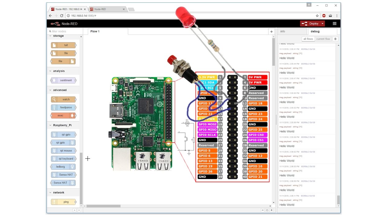
Now open a browser, I use Chrome, and enter the pi IP address noted earlier followed by :1880 i.e. something like 192.168.0.8:1880
You should now have the Node Red programming page in view as below:
You can now follow the Node Red examples starting at 33:00 or move straight on to a tiny bit of additional setup and loading the first flow that will show the link to MQTT and be ready to drive our switch.
The additional setup needed is to add the dashboard items that enable a web interface.
These are shown on the
at 14:14.
Follow the instructions to load node-red-dashboard.
Now we can have a little play and show MQTT working and being driven by Node-Red. This is not on the video but is key to this project. You can either follow my instructions and/or import the flows from the NRtest1.txt file attached.
First add an input inject node and an output mqtt node and link them together.
Double click the inject node (that initially is labelled timestamp). In the Payload section use the twiddly to change to string and enter: Hello from me. Leave topic blank as we can enter this in the MQTT node. Click Done
Now double click the MQTT node. Click the pencil icon to the right of the Server section. This opens a new dialog. Enter: localhost in the Server section. Click Add. Now, back in the Edit mqtt out node, enter our topic in the Topic section: hello/world . Set QoS to 1. Click Done. Now click Deploy. You should see a green blob and ‘connected’ below the mqtt node.
Now add two more nodes – input mqtt and output debug, and connect these together. Now double click the input mqtt node and enter hello/world in the topic section. The server should already show localhost:1883. Set QoS to 1. Click Done. Then click Deploy and click the debug tab on the right hand pane. Now click the grey square on the left of the ‘Hello from me’ inject node. This sends the text payload to the MQTT broker with the topic hello/world. The broker knows that the mqtt input node has subscribed to the same topic and so forwards the payload. The mqtt input node then sends this to the debug tab (RHS) and the text ‘Hello from me’ should appear.
This ticks another box as we have Node Red talking to our MQTT broker. Note that Node Red is just a client to the broker – like the Sonoff devices we will connect later. It however enables sophisticated automation and provides a great user interface.
Now we can make a couple of small changes and set up the flows for our Sonoff switch.
So delete the input inject node (click to highlight and press delete key). Now add a switch from the dashboard section and connect it to the mqtt output. Double click switch. Click the pencil on the right of Group. Enter into Name:Light. Then click the pencil to the right of Tab and enter into the Name section: Lounge . Click Add/Update and Add/Update again. Now, back in the Edit switch node, set the on and off Payloads. Use the twidlys to select string and enter ON for the On payload and OFF for the OFF payload. Click Done
Now go to each of the mqtt nodes and change the Topic to cmnd/sonoff/POWER . If copying and pasting, check you have not included a space at the end. This is a different topic and will not work with the Sonoff. Finding a stray space can take an hour or so – believe me! I also went to the dashboard>Theme and selected: Dark. Click Deploy and select the debug tab.
Now open a new browser session in a new window and size it like a mobile phone over the Node Red session. Enter the address : your Pi IP address:1880/ui/#/0 i.e. something like 192.168.0.8:1880/ui/#/0 . You should see a screen with Lounge and Light and switch. Click the switch on and then off. The debug window should show the ON and OFF payloads. Now if you wish also log on via a mobile as well. Note that the switch position is synchronised. It does not matter that our Sonoff is not yet connected. When it is, by subscribing to the Topic, it will pick up the message/payload and act on it.
A last little step is to make Node Red start automatically after the Pi boots up.
Node Red has a guide at: https://nodered.org/docs/hardware/raspberrypi
However the files needed are already loaded so no installation is required.
To then enable Node-RED to run automatically at every boot and upon crashes enter (open PuTTY session):
sudo systemctl enable nodered.service
If you ever need to disable this enter:
sudo systemctl disable nodered.service
Now shutdown the pi with sudo shutdown now and remove power.
This now has our Pi locked and loaded ready for action. We have our PC/mobile phone connecting to Node Red and this talking to our MQTT server. This has been a long haul and worth a big pat on the back. Well done. I found the next, Arduino bit, a good deal easier!
Step 5: Setting Up the Arduino System for Reprogramming Sonoff Devices
All the info to do this is at the Sonoff-Tasmota GitHub. The only part I had difficulty with was the Topic text – but I have cunningly got you to enter this already!
Go to https://github.com/arendst/Sonoff-Tasmota
You will find the setup instructions on the Wiki tab in the Upload tools section: https://github.com/arendst/Sonoff-Tasmota/wiki/Arduino-IDE
Rather than go through every step I will just note key aspects that I felt were important or got stuck on.
The instructions are good but need careful attention to detail. I was tripped up by there being a need for an ESP8266 folder within a folder that was within another folder named ESP8266 and hence missed out two levels.
I followed the recommendation for an entirely separate Arduino setup. I created a new folder called ‘ArduinoSonoff’ that is separate to my existing Arduino folder. The setup is quite advanced and hence keeping it separate is a very good idea. If this is your first Arduino setup make sure you install it a second time in an ‘Arduino’ or other folder for any other Arduino work, including work on ESP8266s.
Download the latest Arduino IDE from https://www.arduino.cc/en/Main/Software . Unzip the file into your new folder.
The instructions include download the Sonoff-Tasmoda system from https://github.com/arendst/Sonoff-Tasmota main page via: Clone or Download>Download ZIP . Unzip the file into your new folder.
Follow the instructions carefully. I didn’t do the Optional: Prepare for OTA upload section. We will leave this for another day.
Now start the Arduino IDE (double click arduino.exe). Load the Sonoff-Tasmota sketch via File>Sketchbook>sonoff . There is no need to do any edits. All the settings are done via a serial connection after the firmware is loaded. These are stored in EEPROM. Hence the firmware can be updated and all the settings retained. This is pretty smart stuff. However you can avoid the need for a couple steps here by going to the user-config.h file and entering your wifi SSID and password and MQTT_HOST (replace ‘domus1’– second reference, with your Pi IP address). Later you may want to enter a MQTT user and password as well. Before downloading check the board settings under Tools. These will need a couple of changes to match the requirements set out in the Wiki. Now click compile (tick icon). It should compile OK. If it does not or if the required board settings are not available then go back and check each step of the setup.
Step 6: Reprogramming a Sonoff Switch
We are now ready to download. At this stage one can either go straight ahead and flash a Sonoff switch or one can first flash an ESP8266 module. I did the latter, partly because my switches had not yet arrived (just arrived as I type this!) but also as a precaution as the flashing of the Sonoff switch is a one way step as the original firmware is not publicly available as far as I am aware. I have a couple of NodeMCU boards. These are easy to connect, having their on-board USB to serial converter. However the nodemcu reset method does not work with this system. So leave the Tools>Reset Method set to “ck”. Do the normal manual flash setup by holding the Flash button (GPIO 0 to ground) while pressing and releasing Reset (Reset to ground). I am not sure if this has a timeout or maybe I didn’t hold GPIO 0 low for long enough but I did need several tries, including doing this while the Arduino IDE is compiling!
If you want to check the responses – the relay output is D6 on NodeMCU boards. On ESP12’s this is GPIO 12. The LED output is D7 (NodeMCU) or GPIO 13 (ESP12’s).
Sonoff switch.
WARNING: I have to say “do not connect to mains under any circumstances where the enclosure is open”. Note that the PCB (at least on the Sonoff Basic (in-line switch) only has ‘single isolation’ distances between the low voltage section and the mains. So one should treat any part of the Sonoff circuit as mains voltage. The Sonoff-Tasmota GitHub does show connection of a temperature and humidity sensor to a Sonoff S20. I would not do this because of isolation concerns. – so if you want to do this get an ESP12 or NodeMCU module and set this up separately with a proper double isolated or earthed power supply.
The Sonoff S20 plug-in switch is a good starting point as it does not need any mains wiring. This can be opened by removing one screw (under the security seal) and prising the case open. The photo below shows where the tags are. Squeezing the case at these points helps.
USB serial converter
My favourite converter is the FTDI version. However this does not have adequate capability to supply the Sonoff 3.3v needs. The FTDI specification says maximum 50ma. The next best alternative is one using the CP2102 chip. This however has a 100ma limit that is still not enough. Clearly many are using this converter direct but there are also reports of loading failing. I would limit the time it is connected as it will warm up under the load. Do this at your own risk. The ideal solution is to have a 3.3v regulator as well, e.g. an AMS1117 3.3. I made up a small PCB to enable this. See Programmer for Sonoff devices.
My sequence for programming is as follows:
Open the Arduino IDE.
Under Tools check the settings are as on the Wiki.
Make any edits required to user_config.h . I set the Wifi SSID and password and MQTT broker address and timezone/daylight savings details.
Click ‘verify’ to check it compiles OK.
Plug the USB serial converter (on its own) to the PC. Note the Port number.
Now disconnect the USB serial lead from the PC and connect it to the Sonoff switch. Check the ground and 3v3 connections are the right way around (ground is connected to the ground plane on the Sonoff PCB).
Hold the programmer so the contacts are secure while also pressing the button.
Now plug the USB lead into the PC, check the port number is correct (in Tools), then click download.
I continue to hold the button throughout the programming because I don’t want to disturb the connections.
When done you should see a screen as below:

The Sonoff needs a couple of bits of information to connect to our system: the local network wifi SSID and password, and the Pi IP address. There are several ways to do this, one of which is to modify the config.ino file as noted earlier. If you have a smartphone you can (after reassembling the switch) press the Sonoff button 4 times fairly quickly to put it into a web-server mode. The LED will flash. I had to try several times to get this to work. Then, on your smartphone look for the new Sonoff network and connect. A webpage will appear where you can set the data required. The Pi IP address goes into hostname. I also changed the second SSID and password to something long and basically unusable.
Alternatively it can be setup via the serial connection just after loading. Open the Arduino Serial Monitor (under Tools).
Commands to enter:
SSId yourWiFiSSID
Password yourWiFiPassword
MqttHost 192.168.x.y (PI IP address)
You can also enter SSId1 and Password1 followed by something long and unusable to effectively disable this.
Now you can box up the Sonoff switch, open Node-Red and the Node-red dashboard and click the switch button and look at the debug tab that should now include the responses from the Sonoff. So we have another major step achieved – our first switch being driven from a PC/smartphone.
Up to now we have not mentioned security. There is the possibility to use encrypted communications. This is quite complex to set up and probably more appropriate where a cloud based broker is being used. There is also the option to add usernames and passwords for all the connected devices and disallowing anonymous users. This is pretty simple to set up. And so now to Security.
Step 7: Security
MQTT allows usernames and passwords for each client. This is easy to setup. It is probably easier to first rename each device and then set their usernames and passwords. This can be done via MQTT commands, and Node-Red is probably the easiest way to send these. First decide on a naming convention. One option is to base names on location and function. Then you will want to record the name(Topic) username and password along with the fallback topic. Note there is also a ‘reset option’ to reset the Sonoff settings to original download (see Wiki Usage>Button Functionality).
Power up the pi and after a few seconds open a browser to Node-Red (IP address:1880).
In Node-Red set up an inject node and link this to an mqtt output and set the mqtt server to localhost . Leave topic, user and password blank as we will set these in the inject node. Also setup an mqtt input node and connect this to a debug node so we can see the responses. Set the mqtt input note to localhost (should already be set) and enter +/+/+ for topic so it catches all traffic.
Enter the following sequence of settings in the inject node.
First check connectivity with
Topic: cmnd/sonoff/Status
Message: 6
click the ‘Inject once on start’. Deploy. We should see debug including 7 lines of data from stat/sonoff/STATUS6
Enter Topic: cmnd/sonoff/Topic andMessage: loungelight. Deploy. This changes the switch name from sonoff to loungelight
The debug tab should show the device restarting with its new name/topic
Topic: cmnd/loungelight/MqttUser
Message: loungelight
Click deploy. A debug should be seen from stat/loungelight/RESULT with {“MtqqUser”:”loungelight”}
Topic: cmnd/loungelight/MqttPassword
Message: loungelightPW (note be more imaginative than this!)
Clear the debug tab and Deploy.
A reply should be seen from stat/loungelight/RESULT with {“MqttPassword”:”loungelightPW”}
Now enter NodeRed and NodeRedPW as username and password in the mqtt out node. This is via the Server pencil icon and security tab in the window that opens. This automatically gets copied over to the other MQTT nodes.
Check again with
Topic: cmnd/loungelight/Status and Message: 6 . Deploy.
And that the response is sent.
So at this point we have renamed our Sonof device so it will listen to cmnd/loungelight/…… topics and will log onto the MQTT sever with username loungelight and password loungelightPW. We have also set a username and password for Node-Red.
Next we have to tell the mosquito MQTT server to only accept clients with usernames and to list the usernames and passwords to be accepted.
The procedure is:
- Stop mosquito
- Create own config file
- Edit config file
- Create password file
- Add users/passwords.
So log in with a new PuTTY session and run through the following commands:
sudo /etc/init.d/mosquitto stop
cd /etc/mosquitto/conf.d/
sudo nano mosquitto.conf This starts the editor.
Add lines:
allow_anonymous false
password_file /etc/mosquitto/conf.d/passwd
require_certificate false
Save and exit (Ctrl+X), Y, enter .
sudo touch passwd This creates a password file and the following instructions add names and passwords.
sudo mosquitto_passwd -b /etc/mosquitto/conf.d/passwd loungelight loungelightPW
sudo mosquitto_passwd -b /etc/mosquitto/conf.d/passwd NodeRed NodeRedPW
sudo /etc/init.d/mosquitto restart
Note when adding a new device you will have to either enter the user and password via the serial port and add these to the password file or temporarily change the mosquitto config file and comment out (add # at start of line) the lines “allow_anonymous false” and “password_file /etc/mosquitto/conf.d/passwd” and then reset these when the details have been sent to the device and added to the password file as above.
We have changed the sonoff name to loungelight and so update the mqtt output node (connected to the switch) to use the topic cmnd/loungelight/POWER .
Click Deploy and check the mqtt nodes show ‘connected’.
Next try the switch button and look for the debug showing the Sonoff switch responding. You will notice that the device shows the change with a topic: stat/loungelight/POWER. So now change the input node that was set to cmnd/sonoff/POWER to stat/loungelight/POWER . We can use this cover a gap in our functionality. The system as initially set up will be synchronised with all logged on users but will not synchronise with switch changes made by pressing the button on the Sonoff switch. So now connect the output of the stat/loungelight/POWER mqtt input node to the switch input (LHS). Now double click the switch and untick the “if msg arrives on input, pass through to output”. This brings up some new options – select ‘switch icon shows state of the input’. Deploy. So now we have a good feedback loop. The dashboard switch position will always change when the Sonoff switch changes, regardless of where the change was initiated.
So we now have a secure, standalone home automation system up and running and ready for expansion to whatever you want it to do. In the next section I will cover some of my experimentation so far and challenges I plan to tackle.
Step 8: Initial Steps for Expansion
I have another Instructable Home Automation Sonoff-Tasmota Sensors LEDs Development Board that shows some of the further capabilities of the Sonoff-Tasmota firmware:
- Temperature and Humidity measurement
- Intruder detection (switch input)
- IR remote (for TVs etc)
- LED strings – both RGB and NeoPixel (individually addressable)
- I2C sensors
For the above I am using a ESP12F and a custom PCB. A NodeMCU and breadboard could equally be used. This enables these additional functions without wiring into a Sonoff device, and hence is a much safer approach. With the temperature input I have been able to complete my electric blanket automation.
Music and Internet Radio can easily be added. This opens up options to have specific stations or albums come on at set times or maybe in response to a visitor (phone) being detected. This associated instructable is at High quality Music Player and Internet Radio with Smartphone Control. Since this is also driven by Node-RED it should even be possible to have more than one sound system and use MQTT communication to drive them.
I have also been exploring Node-Red, including sending emails and making voice alerts. There is also the potential for the system to detect when you are in/out – by pinging your mobile phone IP address. Node-Red can also access weather and news – so one can add information as well as do automation.
There are a few tricks to be learned – but these become dead easy second time around.
Another avenue is adding a display to the pi to show the dashboard. This is ‘work in progress’ – or in other words I am not too happy. The display I got is difficult to rotate into portrait mode and the Chromium browser is painfully slow. An alternative would be to pick up an old tablet on ebay and use that. I may try with a Pi 2 and see if that delivers enough of an improvement (model B used for this development).
I hope this gets you started and has your imagination buzzing. The potential scope is huge. One could even modify the Sonoff code for other sensors if needed.
Overall I have been amazed at what this system can do. My original objective was to just drive a switch from a smartphone in a reliable manner via a standalone system. I had had visions of needing to manage servers and clients and writing html for a user interface. Where this ended up is way ahead of this, with greater security, excellent reliability, fantastic user interface, drag and drop programming and huge potential for expansion. And all this with much less effort.\
Step 9: Addendum – Loading From Raspbian Stretch Lite
This option avoids the bloatware that comes with the full Raspbian Stretch version. Most of this will not be needed when using a Pi for home automation. However Node-Red does have to be installed.
Proceed as in Step 1 but using Raspbian Stretch Lite rather than Raspbian Stretch.
Instead of Step2 do the following:
sudo apt -y install npm
npm -v should return: 1.4.21 or later
sudo npm install -g n
sudo n 8.9.0
We can now use node packet manager to instal Node-Red:
sudo npm install node-red –global –unsafe-perm
This will give a couple of error messages because of an incorrect address. The system however does a ‘source compile’ to correct this problem. If you repeat the instruction above (not necessary) the errors do not occur.
We now have Node-Red and its supporting packages installed and can move on to Step 3, loading mosquitto.
About The Author
Hassan Zaka
I am an expert in accounting and possess diverse experience in technical writing. I have written for various industries on topics such as finance, business, and technology. My writing style is clear and simple, and I utilize infographics and diagrams to make my writing more engaging. I can be a valuable asset to any organization in need of technical writing services.
Follow Us:LinkedinTwitter


